
Flüssigsilikonkautschuk wird in der Regel für elektrische Isolierungen, flexible Dichtungen und den Einsatz unter extremen Temperaturen verwendet. Durch die Einarbeitung elektrisch leitfähiger Füllstoffe in die Silikonformulierung können Hersteller leitfähige LSR-Bauteile herstellen, die die Flexibilität eines Elastomers mit einem kontrollierten elektrischen Widerstand verbinden.
Leitfähiger Flüssigsilikonkautschuk kann für die elektromagnetische Abschirmung, den antistatischen Schutz, elektrische Kontakte, Widerstandsheizungen, die Hochspannungsfeldsteuerung sowie weitere elektrische oder elektronische Anwendungen eingesetzt werden. Shin-Etsu führt leitfähige Flüssigsilikonmaterialien für die elektromagnetische Abschirmung, antistatische Dichtungen und Klebstoffe an, während Momentive und Dow leitfähige LSR-Typen für Kabelzubehör und Komponenten zur Kontrolle elektrischer Spannungen anbieten.
Die Auswahl von leitfähigem LSR sollte jedoch nicht allein anhand des Aussehens oder der Härte erfolgen. Sein elektrisches Verhalten hängt vom Füllstoffsystem, der Füllstoffkonzentration, der Formgeometrie, dem Anpressdruck, den Verarbeitungsbedingungen und der Einsatzumgebung ab.
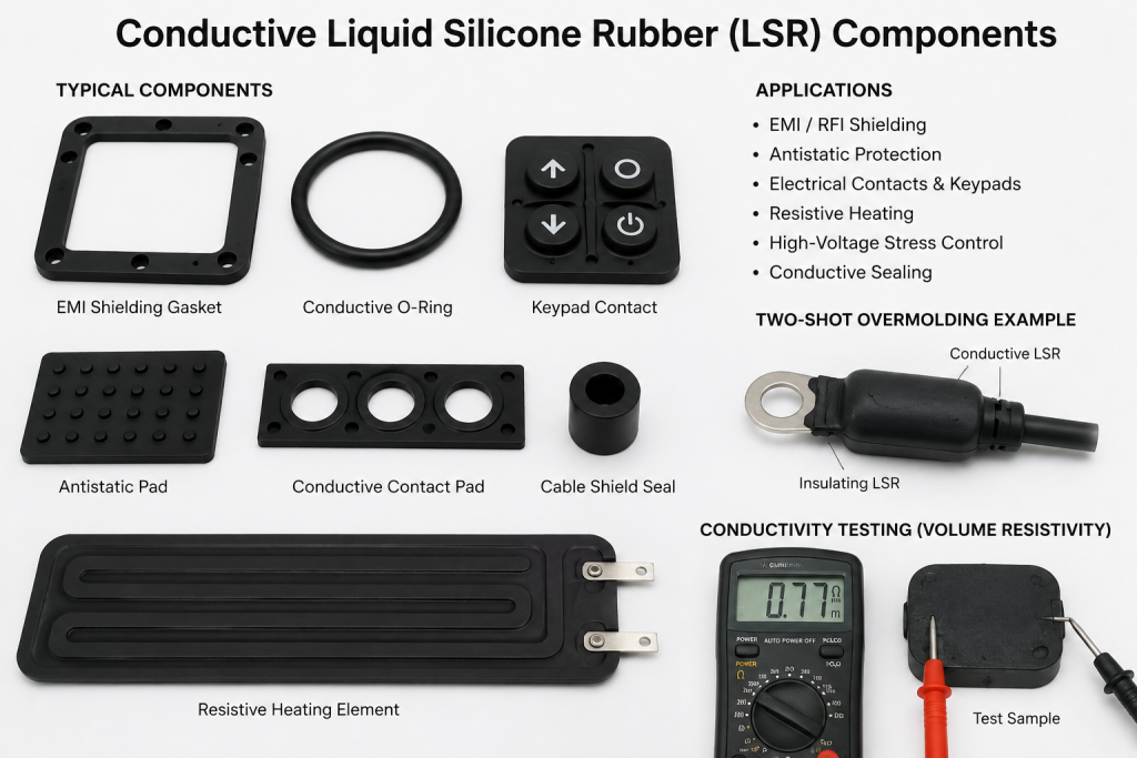
Eine erfolgreiche kundenspezifische Komponente muss daher ein Gleichgewicht zwischen der Leitfähigkeit und folgenden Faktoren herstellen:
- Flexibilität
- Reißfestigkeit
- Kompressionsleistung
- Maßgenauigkeit
- Formbarkeit
- Temperaturbeständigkeit
- Umweltverträglichkeit
- Haftung auf anderen Materialien
In diesem Artikel werden die wichtigsten Eigenschaften, Anwendungsbereiche und fertigungstechnischen Aspekte des kundenspezifischen Formens von leitfähigem LSR erläutert.
Was ist leitfähiger Flüssigsilikonkautschuk?
Flüssigsilikonkautschuk, üblicherweise mit LSR abgekürzt, ist im Allgemeinen ein zweikomponentiges, platinvernetztes Elastomer, das für das Flüssigspritzgießen entwickelt wurde. Es ermöglicht eine schnelle Aushärtung, eine automatisierte Fertigung und das präzise Formen dünner oder komplexer Bauteile. (Momentive)
Herkömmlicher Silikonkautschuk ist in der Regel ein elektrischer Isolator. Leitfähiges LSR wird mit Kohlenstoff oder anderen elektrisch leitfähigen Materialien modifiziert, die leitfähige Bahnen durch das ausgehärtete Elastomer bilden. Shin-Etsu beschreibt leitfähige Silikonprodukte als Silikonmischungen, die Kohlenstoff und andere leitfähige Materialien enthalten und dabei die charakteristische Flexibilität und Umweltbeständigkeit von Silikonkautschuk beibehalten.
Die endgültige Verbindung kann für folgende Zwecke konzipiert sein:
- Geringer elektrischer Widerstand
- Ableitung statischer Elektrizität
- Abschirmung gegen elektromagnetische Störungen
- Gesteuerte ohmsche Erwärmung
- Steuerung des elektrischen Feldes
- Druckabhängige Kontaktschaltung
Der Begriff leitfähiges Silikon ist daher zu allgemein gefasst, um als vollständige Materialspezifikation zu dienen. Ein Produkt, das zur Ableitung statischer Elektrizität bestimmt ist, erfordert möglicherweise einen ganz anderen spezifischen Widerstand als eine Dichtung, die Strom leiten oder empfindliche Elektronik abschirmen soll.
Wie leitfähige Füllstoffe elektrische Leitfähigkeit erzeugen
Das Silikonpolymer selbst bleibt elektrisch isolierend. Die Leitfähigkeit wird durch die Einarbeitung leitfähiger Partikel in die gesamte Formulierung erreicht.
Mit steigender Füllstoffkonzentration kommen die Partikel miteinander in Kontakt und bilden durchgehende elektrische Leitungswege. Unterhalb dieser Leitfähigkeitsschwelle kann der Widerstand extrem hoch bleiben. Im Bereich nahe der Schwelle kann bereits eine relativ geringe Änderung der Füllstoffkonzentration oder der Dispersion zu einer starken Änderung des spezifischen Widerstands führen.
Shin-Etsu berichtet, dass handelsübliche leitfähige Silikonkautschuke in der Regel einen spezifischen Volumenwiderstand zwischen etwa 0,01 und 10 Ω·m aufweisen. Das Unternehmen weist zudem darauf hin, dass es schwierig sein kann, einen konstanten Widerstand in bestimmten Zwischenbereichen aufrechtzuerhalten, da bereits geringe Änderungen des Kohlenstoffgehalts zu erheblichen Widerstandsänderungen führen können. (Shin-Etsu Silikon)
Dies hat mehrere praktische Konsequenzen:
- Ein Kunde sollte einen akzeptablen Widerstandsbereich angeben, anstatt lediglich “leitfähiges Silikon” zu verlangen.”
- Der Hersteller muss für eine gleichmäßige Verteilung und Durchmischung des Füllstoffs sorgen.
- Die Prüfkörper sollten die endgültige Formdicke und die Verarbeitungsbedingungen widerspiegeln.
- Die Leitfähigkeit sollte über mehrere Produktionschargen hinweg bewertet werden.
- Die elektrischen Eigenschaften des fertigen Bauteils sollten geprüft werden und nicht allein aus den Rohstoffdaten abgeleitet werden.
Leitfähiges LSR ist nicht dasselbe wie wärmeleitfähiges LSR
Elektrische Leitfähigkeit und Wärmeleitfähigkeit sind unterschiedliche Materialeigenschaften.
Elektrisch leitfähiges LSR ist so formuliert, dass es elektrischen Strom leitet, statische Aufladung reguliert oder mit einem elektrischen Feld interagiert.
Wärmeleitendes LSR ist in erster Linie darauf ausgelegt, Wärme von elektronischen Bauteilen abzuleiten. Je nach Füllstoffsystem kann es dennoch elektrisch isolierend sein.
Momentive unterscheidet zwischen elektrisch leitfähigen Formulierungen und wärmeleitfähigen, spritzgießbaren LSR-Produkten und zeigt damit, dass für die beiden Funktionen unterschiedliche Kriterien bei der Materialauswahl gelten. (Momentive)
In einer Projektspezifikation sollte eindeutig angegeben werden, ob die Komponente Folgendes erfordert:
- Elektrische Leitfähigkeit
- Wärmeleitfähigkeit
- Beide Immobilien
- Wärmeleitfähigkeit bei elektrischer Isolierung
Werden diese Anforderungen verwechselt, kann dies zu Materialversagen oder elektrischen Sicherheitsrisiken führen.
Zu spezifizierende wesentliche elektrische Eigenschaften
Volumenwiderstand
Der spezifische Volumenwiderstand gibt den elektrischen Widerstand durch den gesamten Körper eines Materials an und wird üblicherweise in Ω·m oder Ω·cm angegeben.
Ein niedrigerer spezifischer Volumenwiderstand deutet im Allgemeinen auf eine höhere elektrische Leitfähigkeit hin.
Der spezifische Volumenwiderstand ist wichtig für:
- Leitfähige Dichtungen
- Hochspannungs-Feldsteuerungskomponenten
- Stromführende Elastomer-Bauteile
- Widerstandsheizelemente
- Leitfähige Kontaktkomponenten
Dow beschreibt sein leitfähiges LSR für Spritzgussanwendungen zur elektrischen Spannungssteuerung als Material mit niedrigem spezifischen Volumenwiderstand.
Der Kunde sollte Folgendes festlegen:
- Zielwert
- Zulässiger Mindestwert
- Maximum acceptable value
- Test specimen thickness
- Prüftemperatur
- Conditioning requirements
- Whether measurements are required before and after aging
Surface Resistance
Surface resistance measures how easily current travels across the surface of a component.
It can be particularly relevant for:
- Static-dissipative surfaces
- Equipment-touch interfaces
- Electronic housings
- Dust-sensitive environments
- Flexible antistatic components
Surface resistance may be affected by contamination, moisture, oils and surface finish. Testing should therefore be performed under conditions representative of actual use.
Contact Resistance
Contact resistance describes the electrical resistance where the silicone touches another conductive material.
The result can depend on:
- Anpressdruck
- Kontaktbereich
- Oberflächenrauheit
- Electrode material
- Oxidation
- Silikonhärte
- Component thickness
- Verunreinigung
- Repeated compression
A raw-material volume-resistivity value does not automatically predict the contact resistance of a finished keypad, switch or conductive gasket.
Resistance Under Compression
Some conductive silicone components are compressed during assembly. Compression can move conductive particles closer together and increase the effective contact area.
The development team should measure resistance at:
- Minimum assembly compression
- Nominal compression
- Maximum compression
- Repeated compression cycles
- Erhöhte Temperatur
- End-of-life conditions
This is especially important for conductive gaskets, contact pads and pressure-sensitive switching components.
EMI Shielding Performance
For electromagnetic interference applications, low resistivity alone may not establish adequate shielding.
Shielding performance can also depend on:
- Filler type
- Component thickness
- Gasket continuity
- Anpressdruck
- Enclosure material
- Joint design
- Frequency range
- Vorbereitung der Oberfläche
- Gaps and fasteners
Shin-Etsu identifies electromagnetic shielding as an application for conductive liquid silicone seals and conductive rubber components. (Shin-Etsu Silikon)
The complete enclosure or assembly should therefore be tested where shielding performance is critical.
Mechanical Properties Still Matter
Adding conductive fillers changes the formulation and may affect the mechanical behavior of the silicone.
Zu den wichtigen Eigenschaften zählen:
- Shore-A-Härte
- Zugfestigkeit
- Dehnung
- Reißfestigkeit
- Druckverformungsrest
- Flex-fatigue resistance
- Resilience
- Abriebfestigkeit
For example, Dow’s conductive stress-control LSR is described as a 30–35 Shore A material with high elongation and specified tensile strength, showing that electrical performance must coexist with mechanical requirements.
A highly conductive formulation may not automatically provide the best:
- Reißfestigkeit
- Dynamic flexibility
- Dichtungsleistung
- Demolding strength
- Thin-wall durability
The selected material must satisfy both electrical and physical requirements.
Temperature and Environmental Performance
Silicone elastomers are commonly selected for their ability to remain flexible across changing temperatures. Conductive formulations can also provide the heat, cold and weather resistance associated with silicone rubber, although exact limits depend on the material grade. Shin-Etsu describes conductive silicone products as providing conductivity together with heat resistance, cold resistance and weatherability. (Shin-Etsu Silikon)
Electrical properties should be evaluated after exposure to relevant conditions, including:
- Hochtemperaturalterung
- Low-temperature storage
- Temperaturwechselbeanspruchung
- Luftfeuchtigkeit
- Wasser
- UV-Strahlung
- Ozon
- Oils or cleaning agents
- Mechanical fatigue
- Long-term compression
Temperature can affect both polymer behavior and electrical resistance. The customer should not assume that room-temperature measurements will remain unchanged throughout the product’s service life.
Major Applications of Conductive LSR
EMI and RFI Shielding Gaskets
Conductive LSR can be molded into flexible gaskets used between electronic housings, covers and access panels.
Potential applications include:
- Kommunikationsgeräte
- Industrial controllers
- Automotive electronic modules
- Battery-system housings
- Sensoren
- Unterhaltungselektronik
- Instrumentation enclosures
The silicone provides flexibility and environmental sealing, while the conductive network helps maintain electrical continuity between mating surfaces.
For effective shielding, the design must prevent discontinuities at:
- Ecken
- Fastener locations
- Gasket joints
- Cable entries
- Housing transitions
Antistatic and Static-Dissipative Components
Conductive or partially conductive silicone may be used to control electrostatic charge.
Beispiele hierfür sind:
- Antistatic seals
- Equipment feet
- Handling pads
- Electronic assembly fixtures
- Schutzhüllen
- Flexible contact surfaces
- Dust-sensitive equipment components
Shin-Etsu specifically identifies antistatic seals, adhesives and protection for electrical or electronic devices as applications for conductive silicone. (Shin-Etsu Silikon)
The target resistance must be carefully controlled. A component designed to dissipate charge does not necessarily need the low resistance required for carrying substantial current.
Conductive Keypads and Switch Contacts
Conductive silicone can be molded into contact pills or integrated switching structures.
When the silicone is pressed, the conductive area connects two circuit-board contacts.
Zu den wichtigen Auslegungsfaktoren zählen:
- Kontaktwiderstand
- Actuation force
- Key travel
- Recovery force
- Contact geometry
- Oberflächenreinheit
- Lebensdauer
- Alignment with the circuit board
Shin-Etsu lists keyboard contact points as a common conductive silicone application.
Resistive Heating Components
Because conductive silicone has electrical resistance, current passing through it can generate heat.
Possible applications include:
- Flexible heater elements
- Anti-condensation parts
- Temperature-maintenance components
- Heated pads
- Specialized industrial devices
Shin-Etsu identifies heater components as one use for conductive silicone rubber.
Heating applications require careful control of:
- Resistance uniformity
- Voltage
- Current
- Component thickness
- Wärmeverteilung
- Maximum surface temperature
- Electrical connections
- Thermische Alterung
- Over-temperature protection
The heater should be evaluated as a complete electrical system rather than only as a molded rubber component.
High-Voltage Cable Accessories
Conductive LSR is used in medium- and high-voltage cable systems for electrical field control.
Applications can include:
- Cable joints
- Cable terminations
- Push-on accessories
- Cold-shrink components
- Stress-control layers
- Switchgear connectors
Momentive states that conductive LSR can be combined with insulating silicone materials to provide electrical field control in push-on joints and cold-shrink cable accessories. (Momentive)
Dow also offers conductive LSR designed for electrical stress-control devices and conductive moldings.
These applications require strict control of:
- Resistivity
- Interface quality
- Layer adhesion
- Geometry
- Luftansammlung
- Verunreinigung
- Insulating-material compatibility
- Long-term electrical aging
Conductive Seals and O-Rings
Conductive silicone can combine sealing with electrical continuity.
Potential applications include:
- Conductive enclosure gaskets
- Grounding seals
- Shielded connector seals
- Equipment access-panel seals
- Specialized O-rings
- Conductive packing components
Shin-Etsu lists conductive gaskets, O-rings, seals and packing among typical molded applications.
The designer must balance low electrical resistance with compression set, sealing force and environmental durability.
Flexible Sensors and Electrodes
Specially developed conductive silicone may also be considered for flexible sensing or electrode structures.
The design may use resistance changes caused by:
- Compression
- Bending
- Stretching
- Contact with another surface
These projects generally require application-specific material characterization because the resistance-strain relationship may be nonlinear and sensitive to geometry, loading history and environmental conditions.
Conductive Filler Selection
Conductive silicone formulations may use carbon or other electrically conductive materials. The filler system influences:
- Electrical resistance
- Farbe
- Viskosität
- Härte
- Reißfestigkeit
- Cost
- Environmental resistance
- Shielding performance
- Processing behavior
Carbon-filled conductive silicone is commonly black. Shin-Etsu’s conductive rubber examples are black products with different volume-resistivity levels. (Shin-Etsu Silikon)
Where a customer requests a light or custom color, the manufacturer must first confirm whether the required conductivity can be achieved with a suitable non-carbon filler system.
A specific filler should not be chosen only because it provides low resistance. The complete formulation must also meet requirements concerning:
- Korrosion
- Galvanic compatibility
- Particle migration
- Mechanische Leistung
- Regulatory restrictions
- Langfristige Stabilität
- Cost
Custom LSR Molding Considerations
Material Metering and Mixing
LSR is typically supplied as a two-part system. Accurate metering and homogeneous mixing are essential for reliable curing and consistent properties. Momentive describes LSR as a two-component, platinum-cured material designed for liquid injection molding. (Momentive)
For conductive grades, poor material control may also create differences in electrical resistance between parts or production batches.
The molding process should control:
- Part A and Part B ratio
- Pumping pressure
- Mischqualität
- Materialtemperatur
- Verweildauer
- Verunreinigung
- Rückverfolgbarkeit von Chargen
Material Viscosity and Cavity Filling
Conductive fillers can change how the LSR flows through the mold.
The mold designer should evaluate:
- Gate size
- Standort des Tors
- Flow length
- Thin-wall sections
- Pressure loss
- Schweißnähte
- Luftblasen
- Entlüftung
- Fill balance
A mold designed for an unfilled general-purpose LSR may not perform identically with a highly filled conductive formulation.
Representative mold-flow trials should be completed using the actual production material.
Conductivity Uniformity
The conductive filler must remain properly dispersed throughout the molded component.
Zu den möglichen Problemen gehören:
- Local resistance variation
- Incomplete conductive paths
- High-resistance weld lines
- Differences between thin and thick sections
- Batch-to-batch inconsistency
- Conductivity variation near gates
Electrical measurements should be taken at multiple positions where uniformity is critical.
Gate and Weld-Line Position
When two flow fronts meet, they form a weld or knit line. Although the silicone may appear fully joined, the filler network at the interface may differ from the rest of the component.
Critical conductive paths should not rely on an unvalidated weld line.
The gate should be positioned to:
- Promote balanced filling
- Minimize air entrapment
- Avoid critical contact areas
- Reduce long flow distances
- Control filler orientation
- Prevent visible gate damage
Entlüftung
Trapped air can create:
- Unvollständige Befüllung
- Oberflächenfehler
- Brandspuren
- Weak areas
- Electrical discontinuities
- Poor overmolding interfaces
LSR molds require precise venting because the material can flow into extremely narrow gaps. Vents must release air without generating unacceptable flash.
Blitzsteuerung
Conductive flash may cause more than a cosmetic defect.
It can create:
- Unintended electrical paths
- Short-circuit risks
- Interference with connector assembly
- Irregular gasket contact
- Contamination inside electronic housings
Critical areas should have clearly defined flash limits on the drawing.
Entformen
High filler loading may affect flexibility and tear resistance. Thin conductive ribs, contact structures and sealing lips can be damaged during ejection.
The component should include:
- Suitable draft and release geometry
- Abgerundete Übergänge
- Adequate wall thickness
- Supported sealing features
- A controlled demolding direction
Reverse tapers and deep undercuts should be reviewed before tooling.
Conductive and Insulating Two-Component Molding
Some applications require conductive and electrically insulating silicone in the same component.
High-voltage cable accessories are one example. A conductive layer may control the electrical field while an insulating silicone layer provides dielectric protection.
Momentive describes conductive Silopren LSR grades designed for combination with insulating LSR in cable joints and terminations. (Momentive)
Two-material LSR molding requires control of:
- Bond strength between layers
- Interface cleanliness
- First-shot curing
- Second-shot adhesion
- Layer thickness
- Conductive-layer position
- Material shrinkage
- Wärmeausdehnung
- Mold alignment
The conductive layer must not extend into areas that require electrical insulation.
Prototype cross-sections and electrical tests should be used to verify the complete interface.
Overmolding Conductive LSR onto Plastic or Metal
Conductive LSR may be overmolded onto:
- Metal terminals
- Busbars
- Cable components
- Kunststoffgehäuse
- Connector bodies
- Sensor structures
- Electronic inserts
Potential benefits include:
- Integrated sealing
- Fewer assembly steps
- Controlled positioning
- Compact construction
- Improved environmental protection
However, adhesion should never be assumed.
The development team must evaluate:
- Substrate material
- Oberflächenbehandlung
- Primer requirements
- Sauberkeit einfügen
- Temperatur eingeben
- Mechanical interlocks
- Mold pressure
- Wärmeausdehnung
- Galvanic compatibility
- Electrical contact location
Self-bonding LSR grades are formulated to adhere to particular thermoplastics or metals, not universally to every substrate. (Momentive)
The actual production-grade insert should be used during adhesion trials.
Designing Electrical Connections
A conductive silicone component must connect reliably to another conductor.
Zu den möglichen Methoden gehören:
- Compression against a metal surface
- Molded contact pads
- Embedded metal inserts
- Clamped connections
- Conductive adhesive
- Mechanical fasteners
The design should avoid relying on uncontrolled point contact.
Zu den wichtigen Faktoren zählen:
- Kontaktbereich
- Anpressdruck
- Metal finish
- Surface oxidation
- Silikondicke
- Montagetoleranz
- Vibration
- Temperaturwechselbeanspruchung
- Repeated disassembly
A larger contact area does not always guarantee lower resistance when compression is uneven. The finished assembly should be measured under minimum and maximum tolerance conditions.
Dimensional Design and Tolerances
Conductive LSR components often serve both electrical and mechanical functions.
Zu den kritischen Dimensionen können gehören:
- Contact thickness
- Sealing-bead height
- Kompressionsabstand
- Electrode spacing
- Conductive-path width
- Insulating clearance
- Einfügeposition
- Gasket perimeter
The drawing should separate:
- Electrical critical dimensions
- Sealing dimensions
- Assembly dimensions
- Cosmetic dimensions
- Reference dimensions
Applying unnecessarily tight tolerances to every feature can increase tooling and inspection costs without improving electrical performance.
Testing Conductive LSR Components
A custom validation plan may include:
Electrical Testing
- Spezifischer Volumenwiderstand
- Surface resistance
- Kontaktwiderstand
- Resistance under compression
- Resistance during stretching or bending
- Current-carrying capacity
- Shielding effectiveness
- Electrical field-control performance
Mechanische Prüfungen
- Härte
- Zugfestigkeit
- Dehnung
- Reißfestigkeit
- Druckverformungsrest
- Repeated compression
- Flex fatigue
- Adhesion or peel strength
Environmental Testing
- Hochtemperaturalterung
- Einwirkung niedriger Temperaturen
- Temperaturwechselbeanspruchung
- Luftfeuchtigkeit
- Water exposure
- UV and ozone
- Flüssigkeitswiderstand
- Vibration
- Salt or corrosive environments
Electrical measurements should be repeated after environmental and mechanical testing.
A component that meets its initial resistance target may change after prolonged compression, heat aging or repeated movement.
Quality-Control Requirements
For production, conductivity should be managed as a controlled characteristic.
A quality plan may include:
- Incoming raw-material identification
- Rückverfolgbarkeit von Chargen
- Metering-ratio control
- First-piece resistance testing
- Maßprüfung
- Sichtprüfung
- Defined electrode fixtures
- Controlled test pressure
- Periodic aging tests
- Statistical monitoring
- Änderungskontrolle
The test method should define the fixture, electrode geometry and applied pressure. Otherwise, two laboratories may obtain different resistance values from the same component.
Common Conductive LSR Design Mistakes
Requesting “Conductive Silicone” Without a Resistance Range
Conductive, antistatic and shielding materials may have very different electrical properties.
Using Raw-Material Data as the Finished-Part Specification
Molded thickness, geometry, pressure and processing can influence electrical performance.
Ignoring Resistance Under Compression
A gasket or contact pad may behave differently at minimum and maximum assembly compression.
Confusing Thermal and Electrical Conductivity
A thermally conductive silicone can remain electrically insulating.
Assuming Every Conductive Grade Is Suitable for EMI Shielding
Shielding depends on the complete enclosure, gasket design and frequency range.
Allowing Conductive Flash in Insulating Areas
Small flash can create an unintended electrical path.
Placing Weld Lines Across a Critical Conductive Path
The conductivity of a weld-line region should be verified before it is used as part of the primary current path.
Ignoring Filler Effects on Moldability
Conductive grades may require different gate, vent and process settings from standard LSR.
Changing Material Grades Without Revalidation
Similar-looking grades can have different fillers, resistance, hardness and processing behavior.
Testing Only at Room Temperature
Electrical and mechanical properties should be checked after representative aging and environmental exposure.
Information Needed for a Custom Conductive LSR Quotation
To receive an accurate quotation, customers should provide:
- 2D and 3D drawings
- Anwendungsbereich des Produkts
- Target volume resistivity
- Surface- or contact-resistance requirements
- Required shielding performance
- Operating voltage and current
- Temperaturbereich
- Umwelteinflüsse
- Silikonhärte
- Compression conditions
- Einsätze aus Kunststoff oder Metall
- Required bonding method
- Expected annual quantity
- Prüfvorschriften
- Applicable testing standards
- Verpackungsvorschriften
For an existing component, a physical sample can also help the manufacturer evaluate:
- Geometry
- Contact areas
- Trennlinien
- Materialhärte
- Montageverfahren
- Potential molding process
Practical Development Process
Step 1: Define the Electrical Function
Determine whether the component is intended for static dissipation, current conduction, shielding, switching, heating or field control.
Step 2: Establish the Resistance Target
Define acceptable minimum and maximum values under specific test conditions.
Step 3: Define Mechanical Requirements
Confirm hardness, compression, sealing force, tear strength and expected movement.
Step 4: Select Candidate Materials
Compare electrical, mechanical, environmental and processing properties.
Step 5: Review the Component Geometry
Evaluate conductive-path continuity, wall thickness, gates, weld lines and contact areas.
Schritt 6: Repräsentative Stichproben erstellen
Use the actual production-grade material and intended molding process.
Step 7: Test the Finished Component
Measure electrical properties using representative fixtures and assembly pressure.
Step 8: Complete Environmental Aging
Repeat testing after heat, humidity, fluids, vibration or mechanical cycling.
Step 9: Conduct Pilot Production
Evaluate batch-to-batch resistance and dimensional consistency.
Step 10: Freeze the Approved Configuration
Control the material grade, supplier, molding process, tool, inserts and test method.
Fazit
Conductive liquid silicone rubber allows manufacturers to combine controlled electrical behavior with the flexibility, temperature performance and design freedom of silicone elastomers.
It can support applications such as:
- EMI shielding
- Antistatic protection
- Elektrische Kontakte
- Flexible heating
- Conductive sealing
- High-voltage field control
- Two-component conductive and insulating assemblies
However, conductive LSR is not a single standardized material.
Successful development requires clearly defined electrical targets, representative finished-part testing and careful control of filler dispersion, mold filling, flash, contact pressure and environmental aging.
The best material is not necessarily the grade with the lowest resistance. It is the grade that provides stable electrical performance while meeting the component’s mechanical, sealing, processing and service-life requirements.
Early cooperation between the product designer, material supplier, mold maker and LSR molding manufacturer can reduce tooling changes and help establish a reliable path from prototype testing to controlled mass production.
Häufig gestellte Fragen
Is ordinary liquid silicone rubber electrically conductive?
No. Standard LSR is generally electrically insulating. Conductive fillers must be incorporated into the formulation to create electrical conductivity.
What fillers are used in conductive silicone?
Carbon and other conductive materials can be added to silicone. The exact filler system depends on the required resistivity, mechanical properties, color and application.
Is conductive silicone always black?
Carbon-filled conductive silicone is normally black. Other filler systems may allow different appearances, but color availability depends on the formulation and required conductivity.
What is the typical resistivity of conductive silicone rubber?
Shin-Etsu reports that many commercial conductive silicone rubbers fall within approximately 0.01–10 Ω·m, although specialized products may be designed outside this range. (Shin-Etsu Silikon)
Can conductive LSR be used for EMI shielding?
Yes. Conductive silicone seals and gaskets can be used in EMI-shielding systems. Shielding performance must be tested in the complete enclosure.
Can conductive LSR also provide environmental sealing?
Yes. A properly designed conductive silicone gasket may provide both electrical continuity and protection against moisture or dust.
Is electrically conductive LSR also thermally conductive?
Not necessarily. Electrical and thermal conductivity are separate properties and must be specified independently.
Can conductive LSR be overmolded onto metal?
Yes, but the insert design, surface condition, adhesion method and electrical contact area must be validated.
Can conductive and insulating silicone be molded together?
Yes. Conductive and insulating LSR layers can be integrated in selected two-component applications, including high-voltage cable accessories. (Momentive)
What is the most important information for a quotation?
The manufacturer needs the drawing, intended electrical function, target resistance range, test conditions, operating environment, hardness, annual quantity and details of any plastic or metal inserts.
 English
  Japanese
  Korean
  German
  French
  Italian
  Spanish
  Dutch
Dutch  Chinese
  Portuguese
  Polish
  Czech
Czech  Hungarian
  Swedish
  Finnish
  Vietnamese
  Thai
Thai  Turkish
  Arabic
  Russian