
矽膠連接器密封件可保護電氣端子免受水分、灰塵、冷凝水及污染物侵蝕。此類密封件廣泛應用於汽車線束、感測器、戶外照明、工業設備、家電、電池系統及船舶電子設備。.
可靠的密封效果不僅取決於選用柔軟的矽膠材料。密封件必須與連接器外殼完美契合,能緊密包覆每根導線,並在插入端子及連接器兩半對接時保持完好無損。.
最重要的設計因素包括:
- 電線與電纜的外徑
- 密封腔尺寸
- 外殼與密封件之間的干涉
- 密封肋的幾何形狀
- 終端插入路徑
- 連接器插合力
- 空腔密封
- 矽膠硬度與壓縮永久變形率
- 閃光與尺寸控制
- 水、壓力及環境測試
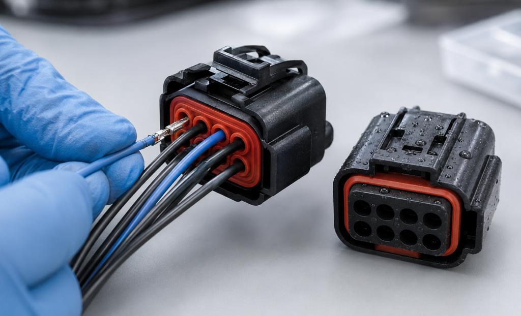
矽膠連接器密封件的種類
一個密封連接器可能包含數種不同的彈性體組件。.
單根線材密封件
將單根線纜密封件壓接或組裝至其中一根線纜上,並插入對應的連接器腔體中。.
它通常在以下範圍內進行密封:
- 電線絕緣層與矽膠密封件
- 矽膠密封圈與連接器外殼
多腔室墊片密封
墊片密封件、後端扣眼或多孔密封件上設有多個孔洞,其位置與連接器的端子位置相對應。.
它能同時封裝多條導線,並可減少組裝零件數量,但其性能在很大程度上取決於型腔對位、壁厚以及未使用孔的管理。.
連接器介面密封件
在相配的連接器外殼之間,會壓緊一個介面密封件或周邊密封件。它可防止水和灰塵從連接器介面滲入。.
徑向軸承座密封圈
徑向密封件套在圓柱形或特定形狀的連接器段外圍,並被壓縮以緊貼於配對的外殼上。.
孔塞
空位塞用於封堵未使用的端子位置。若在線纜密封件中留下空孔,可能會形成通往連接器的直接漏電路徑。.
TE Connectivity 指出,密封件與空腔塞是其重型連接器系統中,用於封閉未使用空腔並維持環境密封的必要元件。. TE 重型密封連接器
包覆成型後端密封件
矽膠也可包覆在導線、嵌件或連接器外殼周圍進行包覆成型,以形成一體式的後端密封結構。此舉可提升固定效果與密封性,但需選用相容的材料、精準控制導線定位,並確保接合可靠。.
了解完整的密封系統
連接器可包含:
- 導線與密封件的接合處
- 密封件與外殼之間的接合面
- 連接器插接介面密封
- 接合處
- 未使用的端子腔體
- 纜線出口或背殼介面
任何一個位置的故障都可能導致整個連接器失效。.
因此,矽膠密封件應作為組裝完成之連接器的一部分進行開發與測試,而非作為獨立的模塑零件。.
商用密封連接器系統正是這種系統化方法的具體體現。以 TE 的 AMPSEAL 連接器系列為例,該系列採用矽膠線材及配對密封件,並針對完整的連接器配置提供防護規格。. TE AMPSEAL 連接器
線封式型腔設計
導線腔是將絕緣導體和端子插入的開口。.
其幾何形狀會影響:
- 密封壓力
- 導線插入力
- 終端插入
- 密封件損壞
- 拉線抗力
- 振動後發生洩漏
- 腔室間隔離
電纜與電線的外徑
線徑並不能直接決定絕緣層的外徑。兩根導體截面積相同的電線,其外徑可能因以下差異而不同:
- 隔熱材料
- 隔熱層厚度
- 製造公差
- 溫度額定值
- 牆體構造
- 表面質地
因此,密封件的規格應採用實際的最小、標稱及最大絕緣直徑——而不僅僅是 AWG 或導體截面積。.
另請參閱:
- 線材橢圓度
- 印刷表面標記
- 縱向凹槽
- 絕緣硬度
- 表面潤滑性
- 因壓接而產生的局部變形
導線與密封件之間的干涉
密封開口通常比電線絕緣層的直徑小,因此矽膠會沿著電線伸展包覆。.
初步干擾值可表示為:
干涉量 (%) = (線材外徑 − 密封孔內徑) ÷ 線材外徑 × 100
並不存在一個適用於所有連接器密封件的通用干涉百分比。.
正確的數值取決於:
- 線徑範圍
- 矽膠硬度
- 絕緣硬度
- 密封肋的數量
- 肋骨幾何形狀
- 接觸長度
- 溫度範圍
- 所需插入力
- 目標壓力或 IP 效能
干擾不足
干擾過少可能會導致:
- 電線沿線的漏水
- 低耐壓性
- 線材的移動
- 振動後的密封不穩定現象
- 最小線徑處的滲漏
過度的干預
過多的干擾可能會導致:
- 高導線插入力
- 摺疊或翻轉的密封唇
- 矽膠撕裂
- 電線絕緣層受損
- 密封件在殼體內的位移
- 終端插入問題
公差分析必須包含「使用最大線徑的最小密封孔」以及「使用最小線徑的最大密封孔」。.
密封肋的幾何形狀
多個密封肋可於導線周圍形成數個接觸區域。.
重要的肋骨變數包括:
- 肋骨內徑
- 肋骨高度
- 肋板厚度
- 肋骨間距
- 根半徑
- 尖端半徑
- 肋骨數量
- 接觸長度
銳利的肋條雖能產生較高的局部壓力,但在插入端子時,可能會割破柔軟的絕緣材料或導致肋條撕裂。圓角肋條通常對組裝公差的容忍度較高。.
間距緊密的肋條可能會形成一個厚實的干涉區,而非多個獨立的密封結構。.
線腔式輸入
經過精確控制的入口倒角或圓角,有助於引導端子與導線穿過矽膠密封圈。.
缺乏適當的引言:
- 端子邊緣可能會割破密封圈。.
- 這根金屬線可能會將密封件擠離原位。.
- 密封肋片可能會摺疊。.
- 組裝力可能會急劇增加。.
進料口應引導端頭,同時避免從第一個密封區去除過多材料。.
終點通道
在許多連接器組件中,壓接端子會先穿過矽膠密封圈,然後才鎖入塑膠外殼中。.
端子可能比電線寬得多,因此密封件必須先暫時拉伸,然後再回彈並緊密包覆在電線絕緣層上。.
評論:
- 最大端點包絡線
- 銳利邊緣與矛狀特徵
- 褶皺翼幾何形狀
- 終端方向
- 插入角度
- 端子與密封件的對準
- 所需插入工具
- 矽膠抗撕裂強度
- 植入後的恢復
即使對塑膠外殼而言安全的端子,仍可能損壞薄的矽膠密封邊條。.
密封件與外殼的配合
墊片密封件或單體密封件的外側必須以受控的壓縮力與外殼緊密貼合。.
外殼介面可採用:
- 徑向干涉
- 軸向壓縮
- 擋肩
- 卡扣式肋條
- 密封件固定座
- 次級鎖
- 包覆成型接合
若密封件過於鬆動,在端子插入時可能會移位,或從其外表面發生滲漏;若尺寸過大,則可能導致外殼變形,或使安裝密封件所需的力過大。.
外殼腔體引線入口
塑膠外殼應設有平滑的導入口,以引導密封件進入其安裝位置。.
應避免:
- 銳利的閘門遺跡
- 密封孔中的拋出痕跡
- 模具不匹配
- 毛刺
- 粗糙的表面
- 陡峭的台階
外殼的密封面應能在連接器插接載荷及溫度變化下保持尺寸穩定。.
密封件的保持
在以下情況下,連接器密封件必須保持在原位:
- 已插入電線
- 各航站樓均提供服務
- 連接器已接合
- 電線已拉好
- 該組件會產生振動
- 壓力作用於密封腔體上
可能的保留功能包括:
- 環向肋條
- 倒角槽
- 塑膠固定器
- 鎖定板
- 一體成型的肩部結構
- 粘合式或包覆成型介面
以 TE 的防水 QCW 連接器為例,該產品結合了多孔密封結構與密封固定器,並具備多項旨在減少密封件插錯的設計特點。. TE QCW 2.0 防水連接器
多腔室墊片密封設計
多腔密封件必須在多條導線周圍維持密封狀態,同時防止壓力在相鄰端子位置之間傳遞。.
重要參數包括:
- 孔距
- 孔徑
- 孔與孔之間的壁厚
- 外周邊厚度
- 每個空腔周圍的支撐結構
- 整體平整度
- 保留位置
- 端子對齊
腔室之間的壁厚
如果相鄰孔洞之間的矽膠隔牆過薄:
- 插入時可能會撕裂。.
- 一個空腔可能會導致另一個空腔變形。.
- 腔室之間可能會發生壓力洩漏。.
- 密封孔可能會合併。.
- 尺寸控制可能會變得困難。.
增加壁厚雖能提升分離效果,但會導致連接器尺寸增大。最終的間距應在電氣間隙、端子幾何形狀、可成型性及密封性之間取得平衡。.
腔對腔洩漏
水未必非得滲入外部才會導致故障。若液體從一個連接器腔體滲漏至另一個,便可能使污染物接觸到敏感的端子。.
IEC 60512-14-6 規定了一項介面密封測試,用以評估連接器介面處的滲水情況,以及各連接器腔體之間的密封性。. IEC 60512-14-6:2006
當某個端子位置可能受到壓力或流體接觸,而相鄰位置則不應受到此類影響時,應納入腔體隔離要求。.
未使用牙洞的管理
墊片密封件中未使用的孔洞必須刻意封堵。.
選項包括:
- 專用型腔塞
- 盲模腔
- 實心假線
- 整合式可穿刺膜
- 一款空缺職位較少的客製化職位公告
腔體塞應與密封件的幾何形狀及所需直徑相符。若使用臨時拼湊的塞子,可能會損壞肋條,或在振動過程中發生失效。.
Test configurations should include:
- All cavities populated
- Minimum intended wire population
- Worst-case plug arrangement
- Adjacent open and populated positions
Interface Seal Design
The connector interface seal is compressed when the plug and receptacle are mated.
常見的設計包括:
- Rectangular perimeter gasket
- O-ring-style seal
- Multi-lip axial seal
- Radial face seal
- Molded housing-integrated seal
Important design parameters include:
- Seal cross-section
- 溝槽尺寸
- Compression percentage
- Mating depth
- Housing flatness
- Corner radii
- Connector latch force
- Compression stops
Corner Design
Rectangular connector seals often experience greater strain at the corners.
用途:
- Smooth internal radii
- Uniform cross-section
- Controlled mold parting lines
- Adequate groove support
Avoid sharp molded corners and abrupt thickness changes that can create tearing or incomplete filling.
Interface-Seal Compression
Insufficient compression can cause leakage and unstable seal contact. Excessive compression can:
- Increase connector mating force
- Distort the housing
- Damage the silicone
- Overload the latch
- Prevent full terminal engagement
- Cause long-term permanent set
The plastic housing should control final compression through defined mechanical stops rather than relying only on operator force.
Understanding Insertion Force
Several different forces may be involved in assembling a sealed connector.
Seal-to-Housing Installation Force
The force required to install the silicone seal into the plastic connector housing.
Terminal and Wire Insertion Force
The force required to push the crimped terminal through the seal and into the housing.
Connector Mating Force
The force required to mate the plug and receptacle, including terminal engagement, interface-seal compression, alignment and latch operation.
Service Removal Force
The force required to remove a terminal or wire during repair.
These forces should be measured separately when diagnosing an assembly problem.
Factors That Increase Insertion Force
- Excessive silicone interference
- High material hardness
- Sharp or thick sealing ribs
- Insufficient lead-in radius
- Rough housing surfaces
- Large terminal crimp wings
- Misalignment
- Cold operating temperature
- Excessive interface-seal compression
- Seal twisting
- Dimensional stack-up
- Unapproved or missing assembly lubricant
Reducing Insertion Force Without Losing the Seal
Potential design improvements include:
- Add a controlled entry radius.
- Use multiple flexible ribs rather than one long tight bore.
- Reduce nonfunctional contact length.
- Improve terminal-edge smoothness.
- Support the seal so it cannot move.
- Optimize silicone hardness.
- Improve housing alignment.
- Use an approved, controlled lubricant when permitted.
- Separate terminal guidance from sealing.
Do not simply enlarge the seal hole to reduce force. This may solve assembly problems while creating leakage at the smallest wire diameter.
Specifying Insertion-Force Testing
The test plan should define:
- Connector and terminal part numbers
- Wire size and insulation type
- Seal material and cavity
- Insertion direction
- Insertion speed
- Test temperature
- Seal conditioning
- Lubrication
- Peak force
- Force-displacement curve
- Acceptable seal movement
- Post-insertion leak test
- Number of repetitions
IEC 60512-13-2 defines a method for mating-connector insertion and withdrawal forces, but explicitly excludes the effects of locking, latching and sealing devices. Therefore, a project-specific test is still required to measure the actual sealed connector assembly. IEC 60512-13-2:2006
材料硬度
Softer silicone can reduce insertion and mating force, while harder silicone may improve handling and retention.
However, hardness does not directly predict:
- Seal force
- 抗撕裂性
- 摩擦
- 壓縮永久變形
- Low-temperature behavior
- Recovery after terminal insertion
ASTM D2240 describes durometer hardness as an empirical indentation measurement and states that it has no simple relationship with a fundamental material property. ASTM D2240-15(2021)
Use hardness as one material-control parameter—not as the complete seal specification.
Tear Strength and Elongation
Connector seals must survive substantial temporary deformation as terminals pass through the holes.
High elongation is useful, but tear strength and defect sensitivity are also important.
評估:
- Terminal passage without tearing
- Repeated terminal service
- Thin ribs
- Flash-trimmed areas
- Parting-line condition
- Cavity-plug installation
A small cut caused during the first assembly can expand during pressure or vibration testing.
Compression Set
The seal remains compressed inside the connector for most of its life. Excessive compression set can reduce contact pressure and create leakage after heat aging.
ASTM D395 evaluates the ability of rubber compounds to retain elastic properties after prolonged compressive stress. ASTM D395-18(2025)
Material-specimen compression-set data are useful for comparison, but assembled connectors should also be leak-tested after thermal aging.
Low-Molecular-Weight Siloxanes
In sensitive electrical applications, volatile low-molecular-weight siloxanes may contribute to contact problems under certain electrical and environmental conditions.
請考慮:
- Low-volatile silicone grades
- Controlled post-curing
- Clean molding and packaging
- Contact-material compatibility
- Customer-specific electrical testing
Shin-Etsu offers silicone grades designed for waterproof automotive wiring-harness seals with reduced low-molecular-weight siloxane content. Shin-Etsu KE-2017-50-A/B
The production material and cure process should be validated with the intended terminal system.
Chemical and Fluid Compatibility
Connector seals may encounter:
- Engine oil
- Transmission fluid
- Grease
- Fuel
- Coolant
- Washer fluid
- 清潔化學品
- Salt water
- Detergents
- Hydraulic fluid
Standard silicone may not be appropriate for every oil or fuel environment. Fluorosilicone or another elastomer may be required for aggressive fluids.
ASTM D471 provides procedures for comparing the effects of liquids on rubber materials and finished articles. The standard also cautions that accelerated testing does not provide a direct correlation with every service condition. ASTM D471-16a(2021)
After fluid exposure, evaluate:
- Volume change
- Hardness change
- Tensile-property change
- Seal dimensions
- Insertion force
- Leakage
- 壓縮恢復
Common Connector Leak Paths
| Leak path | Likely cause |
|---|---|
| Along wire insulation | Insufficient interference, wire grooves or folded ribs |
| Around the outside of the seal | Incorrect housing fit or seal displacement |
| Through an unused cavity | Missing or incorrect cavity plug |
| Between adjacent cavities | Thin cavity walls, tearing or poor housing support |
| At the mating interface | Low compression, housing distortion or damaged perimeter seal |
| Through a torn terminal path | Sharp terminal edge or excessive insertion force |
| Along the mold parting line | Flash, mismatch or surface defect |
| After heat aging | Compression set or material degradation |
| After vibration | Wire motion, fretting or loss of seal retention |
| After fluid exposure | Swelling, softening or loss of mechanical properties |
IP Ratings and Connector Sealing
IEC 60529 classifies enclosure protection against access, solid foreign objects and water ingress. An IP rating applies to the complete tested connector or enclosure assembly—not to the silicone component alone.
For automotive electrical equipment, ISO 20653:2023 defines IP protection requirements and confirmation tests against foreign objects, water and access. ISO 20653:2023
When a seal supplier says a component is “suitable for IP67,” confirm:
- Connector housing
- Mated or unmated condition
- Wire sizes
- Cavity plugs
- Backshell requirement
- Assembly procedure
- Test standard
- Temperature conditioning
- Water-test conditions
TE, for example, lists different degrees of protection for some sealed connector systems depending on the complete configuration and use of rear protection. TE AMPSEAL 16 connector housings
Connector Leak-Test Methods
Pressure-Decay Testing
The connector is pressurized, isolated and monitored for pressure loss.
重要的變數包括:
- Test pressure
- Stabilization time
- Test duration
- Internal volume
- 溫度
- Allowable decay
- Fixture leakage
Vacuum-Decay Testing
The assembly is evacuated and monitored for pressure change. This can be useful when positive pressure might displace the seal differently from actual service.
Bubble-Immersion Testing
The connector is pressurized and submerged. Escaping bubbles help locate the leak path.
This method is useful for diagnosis but should use a defined pressure, immersion depth and observation period.
Waterproof Immersion Testing
IEC 60512-14-4 specifies a test for connector sealing against water ingress under defined pressure and time conditions. IEC 60512-14-4:2006
Low-Pressure Immersion Testing
IEC 60512-14-5 assesses sealing by exposing a connector assembly to low pressure while immersed in a salt solution. IEC 60512-14-5:2006
High-Pressure Water Testing
Automotive and exposed industrial connectors may require spray or pressure-wash testing according to the applicable product standard. Backshells or rear protection may be required for the stated rating.
Test Before and After Environmental Exposure
An initial leak test is not enough.
Repeat sealing tests after relevant exposure to:
- High-temperature aging
- Low-temperature conditioning
- 熱循環
- Temperature shock
- 濕度
- 振動
- Mechanical shock
- Wire pull
- Cable bending
- Connector mating cycles
- Fluid immersion
- Salt spray
- Pressure cycling
A seal may pass initially but leak after its compression force decreases or the wire moves inside the cavity.
Wire Pull and Strain Relief
The connector seal should not be expected to carry the entire cable load unless specifically designed and validated for that function.
Wire retention may depend on:
- Terminal locking lance
- Secondary lock
- Crimp quality
- Seal friction
- Backshell
- Harness clamp
- Cable strain relief
Excessive wire movement can disturb the seal even if the terminal remains electrically connected.
Use an external harness restraint where cable loads, vibration or repeated movement could reach the sealed connector.
Manufacturing Custom Silicone Connector Seals
Connector seals are commonly produced by:
- Liquid silicone rubber injection molding
- 壓縮成型
- 轉注成型
- Multi-material overmolding
LSR molding is especially suitable for high-volume seals with small ribs and multiple cavities, but tooling and processing must control flash precisely.
Tooling Considerations
Core Pins
Each wire cavity is formed by a small core pin. Pin diameter, alignment and surface finish directly affect sealing and insertion force.
Misaligned pins can create:
- 壁厚不均
- Off-center cavities
- Thin cavity walls
- Variable interference
- Cavity-to-cavity leakage
Gate Location
Avoid placing the gate vestige on:
- Wire sealing ribs
- Perimeter sealing surfaces
- Thin cavity walls
- Terminal entry areas
發洩
Trapped air can create short shots or burns in thin sealing ribs. Venting should be placed at predicted end-of-fill regions without producing excessive flash.
Mold Parting Line
Keep the parting line away from critical sealing surfaces where possible. Flash inside a wire hole can increase insertion force or cut the insulation.
Shrinkage and Cavity Balance
Multi-cavity molds should be evaluated by mold cavity. Combining all measurements can hide one cavity with a shifted hole or undersized seal feature.
Inspection Methods
Production inspection may include:
- Optical measurement of cavity diameter
- Vision inspection for blocked holes
- Pin gauges or controlled plug gauges
- Outer-profile inspection
- Seal weight monitoring
- 快速檢查
- Hardness testing on suitable specimens
- Wire-insertion-force testing
- Pressure-decay testing
- Cavity-to-cavity leak testing
Soft silicone can deform during contact measurement. The measurement method and gauge force must be controlled.
Common Seal Failures
| Failure | Possible cause | Corrective direction |
| Wire insertion force too high | Excessive interference or poor lead-in | Optimize ribs, hole size and entry geometry |
| Seal tears during terminal insertion | Sharp terminal or low tear strength | Smooth terminal path and revise material |
| Seal pushes out of housing | Insufficient retention | Add retainer or revise housing engagement |
| Leakage at minimum wire size | Hole too large or rib compression too low | Review tolerance and sealing-rib geometry |
| Wire insulation is damaged | Excessive local pressure or sharp ribs | Increase rib radius and reduce interference |
| Connector will not fully mate | Interface seal compression too high | Review groove, stops and material hardness |
| Unused cavity leaks | Missing or incorrect plug | Use validated cavity plugs |
| Adjacent cavity leaks | Thin wall or seal damage | Increase separation and housing support |
| Failure after thermal aging | Compression set or material incompatibility | Review compound and compression |
| Variable results by cavity | Tool-core misalignment or flash | Improve tooling and cavity-specific inspection |
Validation Plan
1. Design and Tolerance Review
請確認:
- Minimum and maximum wire OD
- Terminal envelope
- Seal-hole dimensions
- Housing cavity dimensions
- Mat-seal pitch
- Interface-seal compression
- Cavity-plug strategy
2. Material Screening
Compare:
- 硬度
- 抗撕裂強度
- 伸長率
- 壓縮永久變形
- 流體阻力
- Low-temperature flexibility
- Low-molecular-weight siloxane requirements
3. Assembly Testing
Measure:
- Seal-installation force
- Terminal and wire insertion force
- 連接器插合力
- Terminal service-removal force
- Seal displacement
4. Initial Leak Testing
Test:
- Wire-to-seal interface
- Seal-to-housing interface
- Mating interface
- Unused cavities
- 腔室間隔離
5. Environmental Conditioning
Complete the required thermal, mechanical and chemical exposures.
6. Final Leak and Electrical Testing
Repeat leak tests and verify:
- Contact resistance
- Insulation resistance
- Dielectric performance
- Terminal retention
- Visual seal condition
7. Pilot Production
Evaluate production parts by:
- Mold cavity
- Material lot
- Wire size
- Housing lot
- Assembly operator
- Environmental condition
詢價單核對清單
Provide the following information when requesting a custom silicone connector seal quotation:
- Connector housing 2D drawing and 3D model
- Terminal drawing and maximum envelope
- Wire sizes
- Minimum and maximum insulation OD
- Insulation materials
- Number and pitch of cavities
- Populated and unused positions
- Cavity-plug requirements
- Target IP rating
- Leak-test pressure and limit
- Insertion-force limit
- Connector mating-force limit
- Wire-pull requirement
- Operating-temperature range
- Fluid and chemical exposure
- Required silicone hardness
- 顏色
- Flammability requirements
- Electrical-contact compatibility
- 年產量
- Inspection and traceability requirements
If the seal dimensions are not yet finalized, provide the complete connector stack-up. The seal supplier can then recommend cavity, rib and interference geometry for prototype testing.
常見問題
How much smaller should a silicone seal hole be than the wire?
There is no universal value. The required interference depends on wire tolerance, insulation hardness, silicone hardness, rib design, insertion force and leakage requirement.
Why is terminal insertion force too high?
Common causes include excessive cavity interference, poor lead-in geometry, high silicone hardness, rough terminal edges, seal misalignment or low assembly temperature.
Can a single mat seal accommodate several wire sizes?
A limited range may be possible, but the smallest wire must still seal while the largest wire and terminal must pass through without tearing the silicone.
Do unused connector cavities require plugs?
Yes, if the seal hole is open and environmental sealing is required. The plug must be designed and validated for the specific cavity.
Does an IP67 seal make the connector IP67?
No. The IP rating applies to the complete connector assembly, including the housing, interface seal, wire seals, cavity plugs and installation method.
How can cavity-to-cavity leakage be prevented?
Use adequate silicone wall thickness, housing support, precise core-pin alignment and undamaged sealing ribs. Validate isolation using a defined pressure test.
Should silicone connector seals be lubricated?
Only use a lubricant approved for the silicone, wire insulation, plastic housing and electrical contacts. The application amount and process must be controlled.
Is silicone suitable for automotive connector seals?
Yes, suitable grades are widely used for automotive wire and interface seals. Fluid exposure, temperature, compression set, electrical-contact compatibility and the required IP test must still be validated.
結論
A reliable silicone connector seal depends on coordinated cavity geometry, controlled interference, manageable insertion force and complete-system leak testing.
The seal must survive terminal passage, connector mating, vibration, thermal aging and fluid exposure while maintaining compression around every wire and housing interface. Early DFM, tolerance analysis and prototype testing can prevent assembly problems and late-stage IP failures.
Send your connector housing, terminal geometry, wire-diameter range, target insertion force and leakage requirement for a custom silicone connector-seal design and molding review.
 English
  Japanese
  Korean
  German
  French
  Italian
  Spanish
  Dutch
Dutch  Chinese
  Portuguese
  Polish
  Czech
Czech  Hungarian
  Swedish
  Finnish
  Vietnamese
  Thai
Thai  Turkish
  Arabic
  Russian