
Silicone connector seals protect electrical terminals from water, dust, condensation and contaminants. They are widely used in automotive wiring harnesses, sensors, outdoor lighting, industrial equipment, appliances, battery systems and marine electronics.
Reliable sealing depends on more than choosing a soft silicone material. The seal must fit the connector housing, compress around every wire and remain undamaged while terminals are inserted and the connector halves are mated.
The most important design factors include:
- Wire and cable outside diameter
- Seal-cavity dimensions
- Housing-to-seal interference
- Sealing-rib geometry
- Terminal insertion path
- Connector mating force
- Empty-cavity sealing
- Silicone hardness and compression set
- Flash and dimensional control
- Water, pressure and environmental testing
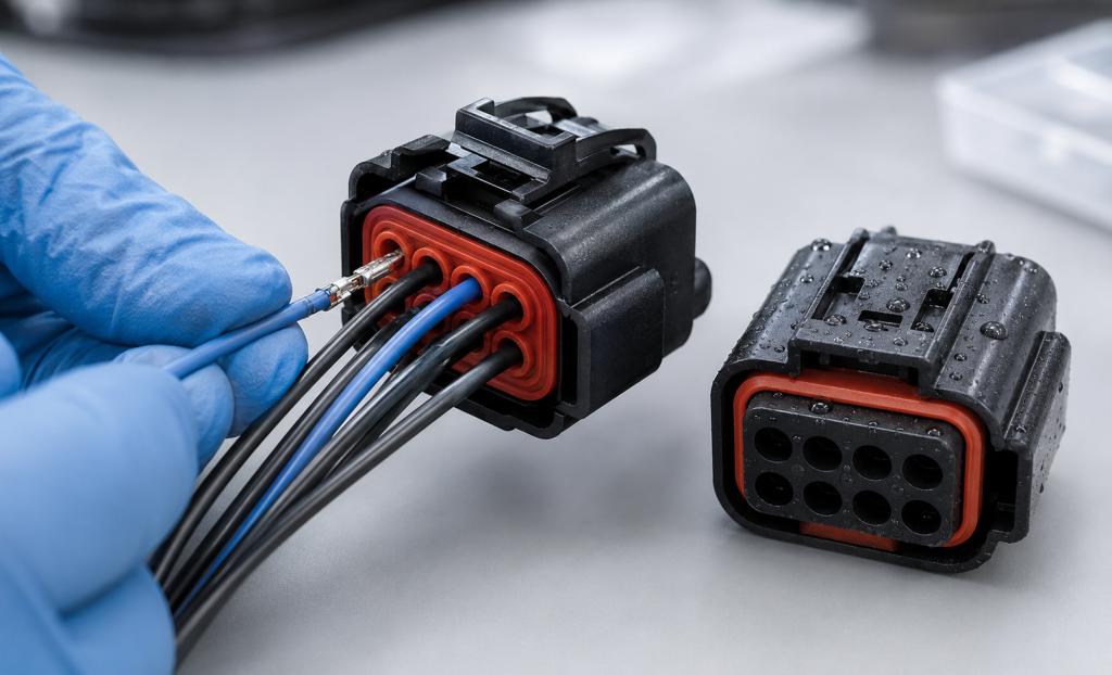
Types of Silicone Connector Seals
A sealed connector may contain several different elastomeric components.
Individual Wire Seal
An individual wire seal is crimped or assembled onto one wire and inserted into a corresponding connector cavity.
It normally seals between:
- The wire insulation and the silicone seal
- The silicone seal and the connector housing
Multi-Cavity Mat Seal
A mat seal, rear grommet or gang seal contains multiple holes corresponding to the connector’s terminal positions.
It seals several wires simultaneously and can reduce assembly-part count, but its performance depends strongly on cavity alignment, wall thickness and unused-hole management.
Connector Interface Seal
An interface or perimeter seal is compressed between the mating connector housings. It prevents water and dust from entering through the connector interface.
Radial Housing Seal
A radial seal fits around a cylindrical or shaped connector section and is compressed against the mating housing.
Cavity Plug
A cavity plug closes an unused terminal position. Leaving an empty hole in a wire seal can create a direct leakage path into the connector.
TE Connectivity describes sealing and cavity plugs as necessary for closing unused cavities and maintaining environmental sealing in its heavy-duty connector systems. TE heavy-duty sealed connectors
Overmolded Rear Seal
Silicone can also be overmolded around wires, inserts or connector housings to create an integrated rear seal. This can improve retention and sealing but requires compatible materials, controlled wire positioning and reliable bonding.
Understand the Complete Sealing System
A connector may include:
- Wire-to-seal interfaces
- Seal-to-housing interfaces
- Connector mating-interface seal
- Housing joints
- Unused terminal cavities
- Cable exits or backshell interfaces
Failure at any one location can compromise the complete connector.
A silicone seal should therefore be developed and tested as part of the assembled connector rather than as an isolated molded component.
Commercial sealed connector systems illustrate this system approach. TE’s AMPSEAL connector family, for example, uses silicone wire and mating seals and specifies protection for the complete connector configuration. TE AMPSEAL connectors
Wire-Seal Cavity Design
The wire cavity is the opening through which the insulated conductor and terminal are inserted.
Its geometry affects:
- Sealing pressure
- Wire-insertion force
- Terminal insertion
- Seal damage
- Wire pull resistance
- Leakage after vibration
- Cavity-to-cavity isolation
Cable and Wire Outside Diameter
Wire gauge does not directly define insulation outside diameter. Two wires with the same conductor cross-section can have different outside diameters because of differences in:
- Insulation material
- Insulation thickness
- Manufacturing tolerance
- Temperature rating
- Wall construction
- Felületi textúra
The seal specification should therefore use actual minimum, nominal and maximum insulation diameters—not only AWG or conductor area.
Also review:
- Wire ovality
- Printed surface markings
- Longitudinal grooves
- Insulation hardness
- Surface lubricity
- Local deformation from crimping
Wire-to-Seal Interference
The seal opening is normally smaller than the wire insulation diameter so the silicone stretches around the wire.
A preliminary interference value can be expressed as:
Interference (%) = (Wire OD − Seal-hole ID) ÷ Wire OD × 100
There is no universal interference percentage suitable for all connector seals.
The correct value depends on:
- Wire-diameter range
- A szilikon keménysége
- Insulation hardness
- Number of sealing ribs
- Rib geometry
- Contact length
- Temperature range
- Required insertion force
- Target pressure or IP performance
Insufficient Interference
Too little interference may cause:
- Water leakage along the wire
- Low pressure resistance
- Wire movement
- Seal instability after vibration
- Leakage at minimum wire diameter
Excessive Interference
Too much interference may cause:
- High wire-insertion force
- Folded or inverted sealing lips
- Silicone tearing
- Damaged wire insulation
- Seal displacement inside the housing
- Terminal insertion problems
The tolerance analysis must include the smallest seal hole with the largest wire and the largest seal hole with the smallest wire.
Sealing-Rib Geometry
Multiple sealing ribs can provide several contact zones around the wire.
Important rib variables include:
- Rib inside diameter
- Rib height
- Rib thickness
- Rib spacing
- Root radius
- Tip radius
- Number of ribs
- Contact length
Sharp ribs can create high local pressure but may cut into soft insulation or tear during terminal insertion. Rounded ribs are generally more tolerant of assembly variation.
Closely spaced ribs may act as one thick interference zone rather than multiple independent seals.
Wire-Cavity Entry
A controlled entry chamfer or radius helps guide the terminal and wire through the silicone seal.
Without an adequate lead-in:
- The terminal edge may cut the seal.
- The wire may push the seal out of position.
- Sealing ribs may fold.
- Assembly force may increase sharply.
The entry should guide the terminal without removing too much material from the first sealing zone.
Terminal Passage
In many connector assemblies, the crimped terminal passes through the silicone seal before it locks into the plastic housing.
The terminal may be significantly wider than the wire, so the seal must stretch temporarily and then recover around the wire insulation.
Review:
- Maximum terminal envelope
- Sharp edges and lance features
- Crimp-wing geometry
- Terminal orientation
- Insertion angle
- Terminal-to-seal alignment
- Required insertion tool
- Silicone tear strength
- Recovery after insertion
A terminal that is safe for the plastic housing may still damage a thin silicone sealing rib.
Seal-to-Housing Fit
The outside of a mat seal or individual seal must engage the housing with controlled compression.
The housing interface may use:
- Radial interference
- Axial compression
- Retaining shoulders
- Snap-in ribs
- A seal retainer
- A secondary lock
- An overmolded bond
If the seal is too loose, it may move during terminal insertion or leak around its outside surface. If it is too large, the housing may distort or seal-installation force may become excessive.
Housing Cavity Lead-In
The plastic housing should include a smooth entry that guides the seal into its installed position.
Avoid:
- Sharp gate vestiges
- Ejector marks in the sealing bore
- Mold mismatch
- Burrs
- Rough surfaces
- Abrupt steps
The housing’s sealing surface should be dimensionally stable under connector-mating loads and temperature exposure.
Seal Retention
A connector seal must remain in position when:
- Wires are inserted
- Terminals are serviced
- The connector is mated
- Wires are pulled
- The assembly vibrates
- Pressure acts on the sealed cavity
Possible retention features include:
- Circumferential ribs
- Undercut grooves
- Plastic retainers
- Locking plates
- Integrated housing shoulders
- Bonded or overmolded interfaces
TE’s waterproof QCW connector, for example, combines a gang seal with a seal retainer and includes features intended to reduce seal mis-insertion. TE QCW 2.0 waterproof connector
Multi-Cavity Mat Seal Design
A multi-cavity seal must maintain sealing around many wires without allowing pressure to pass between adjacent terminal positions.
A fontos paraméterek között szerepelnek:
- Cavity pitch
- Hole diameter
- Wall thickness between holes
- Outer perimeter thickness
- Housing support around each cavity
- Overall flatness
- Retainer position
- Terminal alignment
Wall Thickness Between Cavities
If the silicone wall between adjacent holes is too thin:
- It may tear during insertion.
- One cavity may distort another.
- Pressure may leak between cavities.
- Seal holes may merge.
- Dimensional control may become difficult.
Increasing wall thickness improves separation but increases connector size. The final pitch should balance electrical clearance, terminal geometry, moldability and sealing.
Cavity-to-Cavity Leakage
Water does not always need to reach the exterior to cause failure. Leakage from one connector cavity to another can allow contamination to reach a sensitive terminal.
IEC 60512-14-6 provides an interfacial sealing test that assesses water ingress at connector interfaces and sealing between individual connector cavities. IEC 60512-14-6:2006
Cavity-isolation requirements should be included when one terminal position may experience pressure or fluid exposure that adjacent positions should not receive.
Unused Cavity Management
Unused holes in a mat seal must be intentionally closed.
Options include:
- Dedicated cavity plugs
- Blind molded cavities
- Solid dummy wires
- Integrated pierceable membranes
- A custom seal with fewer open positions
The cavity plug should match the seal geometry and required diameter. Improvised plugs may damage the ribs or fail during vibration.
Test configurations should include:
- All cavities populated
- Minimum intended wire population
- Worst-case plug arrangement
- Adjacent open and populated positions
Interface Seal Design
The connector interface seal is compressed when the plug and receptacle are mated.
A leggyakoribb kivitelek a következők:
- Rectangular perimeter gasket
- O-ring-style seal
- Multi-lip axial seal
- Radial face seal
- Molded housing-integrated seal
Important design parameters include:
- Seal cross-section
- A horony méretei
- Compression percentage
- Mating depth
- Housing flatness
- Corner radii
- Connector latch force
- Compression stops
Corner Design
Rectangular connector seals often experience greater strain at the corners.
Use:
- Smooth internal radii
- Uniform cross-section
- Controlled mold parting lines
- Adequate groove support
Avoid sharp molded corners and abrupt thickness changes that can create tearing or incomplete filling.
Interface-Seal Compression
Insufficient compression can cause leakage and unstable seal contact. Excessive compression can:
- Increase connector mating force
- Distort the housing
- Damage the silicone
- Overload the latch
- Prevent full terminal engagement
- Cause long-term permanent set
The plastic housing should control final compression through defined mechanical stops rather than relying only on operator force.
Understanding Insertion Force
Several different forces may be involved in assembling a sealed connector.
Seal-to-Housing Installation Force
The force required to install the silicone seal into the plastic connector housing.
Terminal and Wire Insertion Force
The force required to push the crimped terminal through the seal and into the housing.
Connector Mating Force
The force required to mate the plug and receptacle, including terminal engagement, interface-seal compression, alignment and latch operation.
Service Removal Force
The force required to remove a terminal or wire during repair.
These forces should be measured separately when diagnosing an assembly problem.
Factors That Increase Insertion Force
- Excessive silicone interference
- High material hardness
- Sharp or thick sealing ribs
- Insufficient lead-in radius
- Rough housing surfaces
- Large terminal crimp wings
- Misalignment
- Cold operating temperature
- Excessive interface-seal compression
- Seal twisting
- Dimensional stack-up
- Unapproved or missing assembly lubricant
Reducing Insertion Force Without Losing the Seal
Potential design improvements include:
- Add a controlled entry radius.
- Use multiple flexible ribs rather than one long tight bore.
- Reduce nonfunctional contact length.
- Improve terminal-edge smoothness.
- Support the seal so it cannot move.
- Optimize silicone hardness.
- Improve housing alignment.
- Use an approved, controlled lubricant when permitted.
- Separate terminal guidance from sealing.
Do not simply enlarge the seal hole to reduce force. This may solve assembly problems while creating leakage at the smallest wire diameter.
Specifying Insertion-Force Testing
The test plan should define:
- Connector and terminal part numbers
- Wire size and insulation type
- Seal material and cavity
- Insertion direction
- Insertion speed
- Test temperature
- Seal conditioning
- Lubrication
- Peak force
- Force-displacement curve
- Acceptable seal movement
- Post-insertion leak test
- Number of repetitions
IEC 60512-13-2 defines a method for mating-connector insertion and withdrawal forces, but explicitly excludes the effects of locking, latching and sealing devices. Therefore, a project-specific test is still required to measure the actual sealed connector assembly. IEC 60512-13-2:2006
Anyagkeménység
Softer silicone can reduce insertion and mating force, while harder silicone may improve handling and retention.
However, hardness does not directly predict:
- Seal force
- Szakadásállóság
- Friction
- Tömörítési alakváltozás
- Low-temperature behavior
- Recovery after terminal insertion
ASTM D2240 describes durometer hardness as an empirical indentation measurement and states that it has no simple relationship with a fundamental material property. ASTM D2240-15(2021)
Use hardness as one material-control parameter—not as the complete seal specification.
Tear Strength and Elongation
Connector seals must survive substantial temporary deformation as terminals pass through the holes.
High elongation is useful, but tear strength and defect sensitivity are also important.
Evaluate:
- Terminal passage without tearing
- Repeated terminal service
- Thin ribs
- Flash-trimmed areas
- Parting-line condition
- Cavity-plug installation
A small cut caused during the first assembly can expand during pressure or vibration testing.
Compression Set
The seal remains compressed inside the connector for most of its life. Excessive compression set can reduce contact pressure and create leakage after heat aging.
ASTM D395 evaluates the ability of rubber compounds to retain elastic properties after prolonged compressive stress. ASTM D395-18(2025)
Material-specimen compression-set data are useful for comparison, but assembled connectors should also be leak-tested after thermal aging.
Low-Molecular-Weight Siloxanes
In sensitive electrical applications, volatile low-molecular-weight siloxanes may contribute to contact problems under certain electrical and environmental conditions.
Consider:
- Low-volatile silicone grades
- Controlled post-curing
- Clean molding and packaging
- Contact-material compatibility
- Customer-specific electrical testing
Shin-Etsu offers silicone grades designed for waterproof automotive wiring-harness seals with reduced low-molecular-weight siloxane content. Shin-Etsu KE-2017-50-A/B
The production material and cure process should be validated with the intended terminal system.
Chemical and Fluid Compatibility
Connector seals may encounter:
- Engine oil
- Transmission fluid
- Grease
- Fuel
- Coolant
- Washer fluid
- Cleaning chemicals
- Salt water
- Detergents
- Hydraulic fluid
Standard silicone may not be appropriate for every oil or fuel environment. Fluorosilicone or another elastomer may be required for aggressive fluids.
ASTM D471 provides procedures for comparing the effects of liquids on rubber materials and finished articles. The standard also cautions that accelerated testing does not provide a direct correlation with every service condition. ASTM D471-16a(2021)
After fluid exposure, evaluate:
- Volume change
- Hardness change
- Tensile-property change
- Seal dimensions
- Insertion force
- Leakage
- Compression recovery
Common Connector Leak Paths
| Leak path | Likely cause |
|---|---|
| Along wire insulation | Insufficient interference, wire grooves or folded ribs |
| Around the outside of the seal | Incorrect housing fit or seal displacement |
| Through an unused cavity | Missing or incorrect cavity plug |
| Between adjacent cavities | Thin cavity walls, tearing or poor housing support |
| At the mating interface | Low compression, housing distortion or damaged perimeter seal |
| Through a torn terminal path | Sharp terminal edge or excessive insertion force |
| Along the mold parting line | Flash, mismatch or surface defect |
| After heat aging | Compression set or material degradation |
| After vibration | Wire motion, fretting or loss of seal retention |
| After fluid exposure | Swelling, softening or loss of mechanical properties |
IP Ratings and Connector Sealing
IEC 60529 classifies enclosure protection against access, solid foreign objects and water ingress. An IP rating applies to the complete tested connector or enclosure assembly—not to the silicone component alone.
For automotive electrical equipment, ISO 20653:2023 defines IP protection requirements and confirmation tests against foreign objects, water and access. ISO 20653:2023
When a seal supplier says a component is “suitable for IP67,” confirm:
- Connector housing
- Mated or unmated condition
- Wire sizes
- Cavity plugs
- Backshell requirement
- Assembly procedure
- Test standard
- Temperature conditioning
- Water-test conditions
TE, for example, lists different degrees of protection for some sealed connector systems depending on the complete configuration and use of rear protection. TE AMPSEAL 16 connector housings
Connector Leak-Test Methods
Pressure-Decay Testing
The connector is pressurized, isolated and monitored for pressure loss.
Important variables include:
- Test pressure
- Stabilization time
- Test duration
- Internal volume
- Temperature
- Allowable decay
- Fixture leakage
Vacuum-Decay Testing
The assembly is evacuated and monitored for pressure change. This can be useful when positive pressure might displace the seal differently from actual service.
Bubble-Immersion Testing
The connector is pressurized and submerged. Escaping bubbles help locate the leak path.
This method is useful for diagnosis but should use a defined pressure, immersion depth and observation period.
Waterproof Immersion Testing
IEC 60512-14-4 specifies a test for connector sealing against water ingress under defined pressure and time conditions. IEC 60512-14-4:2006
Low-Pressure Immersion Testing
IEC 60512-14-5 assesses sealing by exposing a connector assembly to low pressure while immersed in a salt solution. IEC 60512-14-5:2006
High-Pressure Water Testing
Automotive and exposed industrial connectors may require spray or pressure-wash testing according to the applicable product standard. Backshells or rear protection may be required for the stated rating.
Test Before and After Environmental Exposure
An initial leak test is not enough.
Repeat sealing tests after relevant exposure to:
- High-temperature aging
- Low-temperature conditioning
- Thermal cycling
- Temperature shock
- Humidity
- Vibration
- Mechanical shock
- Wire pull
- Cable bending
- Connector mating cycles
- Fluid immersion
- Salt spray
- Pressure cycling
A seal may pass initially but leak after its compression force decreases or the wire moves inside the cavity.
Wire Pull and Strain Relief
The connector seal should not be expected to carry the entire cable load unless specifically designed and validated for that function.
Wire retention may depend on:
- Terminal locking lance
- Secondary lock
- Crimp quality
- Seal friction
- Backshell
- Harness clamp
- Cable strain relief
Excessive wire movement can disturb the seal even if the terminal remains electrically connected.
Use an external harness restraint where cable loads, vibration or repeated movement could reach the sealed connector.
Manufacturing Custom Silicone Connector Seals
Connector seals are commonly produced by:
- Liquid silicone rubber injection molding
- Tömörítőformázás
- Transzferformázás
- Multi-material overmolding
LSR molding is especially suitable for high-volume seals with small ribs and multiple cavities, but tooling and processing must control flash precisely.
Tooling Considerations
Core Pins
Each wire cavity is formed by a small core pin. Pin diameter, alignment and surface finish directly affect sealing and insertion force.
Misaligned pins can create:
- Uneven wall thickness
- Off-center cavities
- Thin cavity walls
- Variable interference
- Cavity-to-cavity leakage
Gate Location
Avoid placing the gate vestige on:
- Wire sealing ribs
- Perimeter sealing surfaces
- Thin cavity walls
- Terminal entry areas
Szellőzés
Trapped air can create short shots or burns in thin sealing ribs. Venting should be placed at predicted end-of-fill regions without producing excessive flash.
Mold Parting Line
Keep the parting line away from critical sealing surfaces where possible. Flash inside a wire hole can increase insertion force or cut the insulation.
Shrinkage and Cavity Balance
Multi-cavity molds should be evaluated by mold cavity. Combining all measurements can hide one cavity with a shifted hole or undersized seal feature.
Inspection Methods
Production inspection may include:
- Optical measurement of cavity diameter
- Vision inspection for blocked holes
- Pin gauges or controlled plug gauges
- Outer-profile inspection
- Seal weight monitoring
- Flash inspection
- Hardness testing on suitable specimens
- Wire-insertion-force testing
- Pressure-decay testing
- Cavity-to-cavity leak testing
Soft silicone can deform during contact measurement. The measurement method and gauge force must be controlled.
Common Seal Failures
| Failure | Possible cause | Corrective direction |
| Wire insertion force too high | Excessive interference or poor lead-in | Optimize ribs, hole size and entry geometry |
| Seal tears during terminal insertion | Sharp terminal or low tear strength | Smooth terminal path and revise material |
| Seal pushes out of housing | Insufficient retention | Add retainer or revise housing engagement |
| Leakage at minimum wire size | Hole too large or rib compression too low | Review tolerance and sealing-rib geometry |
| Wire insulation is damaged | Excessive local pressure or sharp ribs | Increase rib radius and reduce interference |
| Connector will not fully mate | Interface seal compression too high | Review groove, stops and material hardness |
| Unused cavity leaks | Missing or incorrect plug | Use validated cavity plugs |
| Adjacent cavity leaks | Thin wall or seal damage | Increase separation and housing support |
| Failure after thermal aging | Compression set or material incompatibility | Review compound and compression |
| Variable results by cavity | Tool-core misalignment or flash | Improve tooling and cavity-specific inspection |
Validation Plan
1. Design and Tolerance Review
Confirm:
- Minimum and maximum wire OD
- Terminal envelope
- Seal-hole dimensions
- Housing cavity dimensions
- Mat-seal pitch
- Interface-seal compression
- Cavity-plug strategy
2. Material Screening
Compare:
- Keménység
- Tear strength
- Elongation
- Tömörítési alakváltozás
- Fluid resistance
- Low-temperature flexibility
- Low-molecular-weight siloxane requirements
3. Assembly Testing
Measure:
- Seal-installation force
- Terminal and wire insertion force
- Connector mating force
- Terminal service-removal force
- Seal displacement
4. Initial Leak Testing
Test:
- Wire-to-seal interface
- Seal-to-housing interface
- Mating interface
- Unused cavities
- Cavity-to-cavity isolation
5. Environmental Conditioning
Complete the required thermal, mechanical and chemical exposures.
6. Final Leak and Electrical Testing
Repeat leak tests and verify:
- Contact resistance
- Insulation resistance
- Dielectric performance
- Terminal retention
- Visual seal condition
7. Pilot Production
Evaluate production parts by:
- Mold cavity
- Material lot
- Wire size
- Housing lot
- Assembly operator
- Environmental condition
RFQ Checklist
Provide the following information when requesting a custom silicone connector seal quotation:
- Connector housing 2D drawing and 3D model
- Terminal drawing and maximum envelope
- Wire sizes
- Minimum and maximum insulation OD
- Insulation materials
- Number and pitch of cavities
- Populated and unused positions
- Cavity-plug requirements
- Target IP rating
- Leak-test pressure and limit
- Insertion-force limit
- Connector mating-force limit
- Wire-pull requirement
- Operating-temperature range
- Fluid and chemical exposure
- Required silicone hardness
- Szín
- Flammability requirements
- Electrical-contact compatibility
- Annual production volume
- Inspection and traceability requirements
If the seal dimensions are not yet finalized, provide the complete connector stack-up. The seal supplier can then recommend cavity, rib and interference geometry for prototype testing.
Gyakran feltett kérdések
How much smaller should a silicone seal hole be than the wire?
There is no universal value. The required interference depends on wire tolerance, insulation hardness, silicone hardness, rib design, insertion force and leakage requirement.
Why is terminal insertion force too high?
Common causes include excessive cavity interference, poor lead-in geometry, high silicone hardness, rough terminal edges, seal misalignment or low assembly temperature.
Can a single mat seal accommodate several wire sizes?
A limited range may be possible, but the smallest wire must still seal while the largest wire and terminal must pass through without tearing the silicone.
Do unused connector cavities require plugs?
Yes, if the seal hole is open and environmental sealing is required. The plug must be designed and validated for the specific cavity.
Does an IP67 seal make the connector IP67?
No. The IP rating applies to the complete connector assembly, including the housing, interface seal, wire seals, cavity plugs and installation method.
How can cavity-to-cavity leakage be prevented?
Use adequate silicone wall thickness, housing support, precise core-pin alignment and undamaged sealing ribs. Validate isolation using a defined pressure test.
Should silicone connector seals be lubricated?
Only use a lubricant approved for the silicone, wire insulation, plastic housing and electrical contacts. The application amount and process must be controlled.
Is silicone suitable for automotive connector seals?
Yes, suitable grades are widely used for automotive wire and interface seals. Fluid exposure, temperature, compression set, electrical-contact compatibility and the required IP test must still be validated.
Következtetés
A reliable silicone connector seal depends on coordinated cavity geometry, controlled interference, manageable insertion force and complete-system leak testing.
The seal must survive terminal passage, connector mating, vibration, thermal aging and fluid exposure while maintaining compression around every wire and housing interface. Early DFM, tolerance analysis and prototype testing can prevent assembly problems and late-stage IP failures.
Send your connector housing, terminal geometry, wire-diameter range, target insertion force and leakage requirement for a custom silicone connector-seal design and molding review.
 English
  Japanese
  Korean
  German
  French
  Italian
  Spanish
  Dutch
Dutch  Chinese
  Portuguese
  Polish
  Czech
Czech  Hungarian
  Swedish
  Finnish
  Vietnamese
  Thai
Thai  Turkish
  Arabic
  Russian