
ซีลต่อต่อแบบซิลิโคนช่วยป้องกันขั้วไฟฟ้าจากน้ำ ฝุ่น ความชื้น และสารปนเปื้อน ซีลเหล่านี้ถูกใช้อย่างแพร่หลายในระบบสายไฟของรถยนต์ เซ็นเซอร์ ระบบไฟส่องสว่างกลางแจ้ง อุปกรณ์อุตสาหกรรม เครื่องใช้ในบ้าน ระบบแบตเตอรี่ และอุปกรณ์อิเล็กทรอนิกส์ทางทะเล.
การปิดผนึกที่เชื่อถือได้ไม่ได้ขึ้นอยู่กับเพียงการเลือกวัสดุซิลิโคนนุ่มเท่านั้น แต่ยังต้องให้ซีลนั้นพอดีกับตัวเรือนของหัวต่อ กดแนบสนิทรอบทุกสายไฟ และไม่เกิดความเสียหายเมื่อใส่ขั้วต่อและประกอบส่วนต่าง ๆ ของหัวต่อเข้าด้วยกัน.
ปัจจัยการออกแบบที่สำคัญที่สุด ได้แก่:
- เส้นผ่านศูนย์กลางภายนอกของสายและเคเบิล
- ขนาดช่องปิดผนึก
- การขัดขวางระหว่างตัวเรือนกับซีล
- รูปทรงของซี่ปิดผนึก
- เส้นทางแทรกเทอร์มินัล
- แรงต่อตัวต่อ
- การปิดผนึกช่องว่าง
- ความแข็งของซิลิโคนและค่าการคืนตัวหลังการบีบอัด
- การควบคุมแสงแฟลชและมิติ
- การทดสอบน้ำ ความดัน และสภาพแวดล้อม
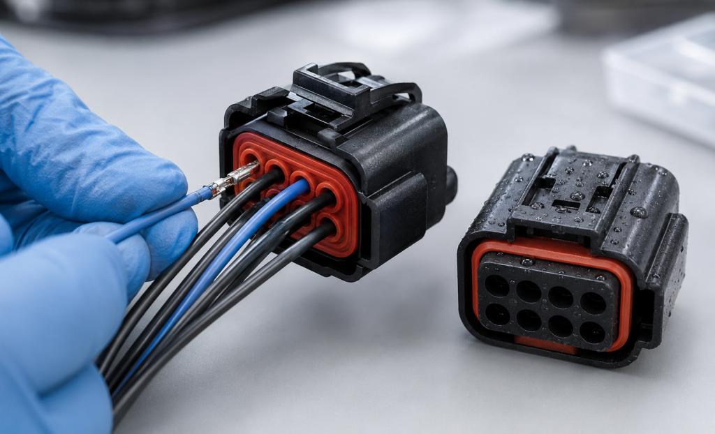
ประเภทของซีลต่อต่อแบบซิลิโคน
หัวต่อแบบปิดผนึกอาจประกอบด้วยชิ้นส่วนยางหลายชนิดที่แตกต่างกัน.
ซีลสายเดี่ยว
สายซีลแต่ละเส้นจะถูกบีบหรือประกอบเข้ากับสายหนึ่งเส้น แล้วใส่เข้าไปในช่องของหัวต่อที่สอดคล้องกัน.
โดยปกติแล้วมันจะปิดผนึกระหว่าง:
- ชั้นฉนวนของสายและซีลซิลิโคน
- ซีลซิลิโคนและตัวเรือนตัวต่อ
ซีลแบบหลายช่อง
ซีลแบบแผ่น, ซีลแบบวงแหวนด้านหลัง หรือซีลแบบกลุ่ม มีรูหลายรูที่สอดคล้องกับตำแหน่งขั้วต่อของตัวเชื่อมต่อ.
มันสามารถปิดผนึกสายหลายเส้นพร้อมกันและช่วยลดจำนวนชิ้นส่วนในการประกอบได้ แต่ประสิทธิภาพของมันขึ้นอยู่กับความตรงกันของช่องแม่พิมพ์ ความหนาของผนัง และการจัดการรูที่ไม่ได้ใช้เป็นอย่างมาก.
ซีลต่อต่อระหว่างส่วนต่อ
ซีลต่อรอยต่อหรือซีลรอบขอบถูกบีบอัดระหว่างตัวเรือนของหัวต่อที่เชื่อมต่อกัน ซึ่งช่วยป้องกันน้ำและฝุ่นไม่ให้เข้าสู่ผ่านรอยต่อของหัวต่อ.
ซีลตัวเรือนแบบรัศมี
ซีลแบบรัศมีจะติดตั้งรอบส่วนต่อแบบทรงกระบอกหรือส่วนต่อที่มีรูปทรงเฉพาะ และถูกบีบให้แนบสนิทกับตัวเรือนที่เชื่อมต่อ.
ปลั๊กช่องว่าง
ปลั๊กช่องว่างใช้ปิดตำแหน่งขั้วต่อที่ไม่ได้ใช้งาน การทิ้งช่องว่างในซีลสายอาจก่อให้เกิดเส้นทางรั่วไหลโดยตรงเข้าสู่ตัวต่อ.
TE Connectivity ระบุว่า การปิดผนึกและปลั๊กช่องว่างเป็นสิ่งจำเป็นสำหรับการปิดช่องว่างที่ไม่ได้ใช้งานและรักษาการปิดผนึกจากสภาพแวดล้อมในระบบตัวต่อแบบทนแรงสูงของบริษัท. TE ตัวต่อแบบปิดกันน้ำสำหรับงานหนัก
ซีลด้านหลังแบบโอเวอร์โมลด์
ซิลิโคนยังสามารถถูกหล่อทับรอบสายไฟ ชิ้นส่วนแทรก หรือตัวเรือนหัวต่อ เพื่อสร้างซีลด้านหลังแบบบูรณาการ ซึ่งสามารถช่วยปรับปรุงการยึดติดและการปิดผนึกได้ แต่จำเป็นต้องใช้วัสดุที่เข้ากันได้ การจัดตำแหน่งสายไฟอย่างควบคุม และการยึดติดที่เชื่อถือได้.
เข้าใจระบบการปิดผนึกอย่างครบถ้วน
ตัวต่ออาจประกอบด้วย:
- จุดต่อระหว่างสายกับส่วนปิดผนึก
- จุดต่อระหว่างซีลกับตัวเครื่อง
- ซีลสำหรับส่วนต่อของตัวเชื่อมต่อ
- ข้อต่อสำหรับโครงสร้างอาคาร
- ช่องเทอร์มินัลที่ยังไม่ได้ใช้
- ช่องออกสายเคเบิล หรืออินเทอร์เฟซแบ็คเชลล์
ความล้มเหลวที่จุดใดก็ตามอาจทำให้ตัวต่อทั้งหมดทำงานผิดปกติ.
ดังนั้น ควรพัฒนาและทดสอบซีลซิลิโคนในฐานะส่วนหนึ่งของตัวต่อที่ประกอบเสร็จแล้ว แทนที่จะเป็นชิ้นส่วนที่หล่อขึ้นรูปแยกต่างหาก.
ระบบต่อสายแบบปิดผนึกเชิงพาณิชย์เป็นตัวอย่างที่แสดงให้เห็นถึงวิธีการออกแบบระบบนี้ ตัวอย่างเช่น กลุ่มผลิตภัณฑ์ต่อสาย AMPSEAL ของ TE ใช้สายซิลิโคนและซีลสำหรับส่วนต่อคู่ และกำหนดระดับการป้องกันสำหรับโครงสร้างต่อสายทั้งหมด. หัวต่อ TE AMPSEAL
การออกแบบช่องว่างแบบปิดด้วยลวด
ช่องว่างของสายคือช่องที่ใช้วางตัวนำที่มีฉนวนและขั้วต่อเข้าไป.
รูปทรงของมันมีผลต่อ:
- ความดันการปิดผนึก
- แรงดันสาย
- การใส่ปลายสาย
- ความเสียหายของซีล
- ความต้านทานต่อแรงดึงของสาย
- การรั่วไหลหลังจากเกิดการสั่นสะเทือน
- การแยกช่องว่างจากช่องว่าง
เส้นผ่านศูนย์กลางภายนอกของสายเคเบิลและสายไฟ
ขนาดสายไม่ได้กำหนดเส้นผ่านศูนย์กลางภายนอกของฉนวนโดยตรง สายสองเส้นที่มีพื้นที่หน้าตัดของตัวนำเท่ากันอาจมีเส้นผ่านศูนย์กลางภายนอกที่แตกต่างกัน เนื่องจากความแตกต่างใน:
- วัสดุฉนวน
- ความหนาของวัสดุฉนวน
- ค่าความคลาดเคลื่อนในการผลิต
- ช่วงอุณหภูมิที่รองรับ
- การก่อสร้างผนัง
- พื้นผิว
ดังนั้น ข้อกำหนดเกี่ยวกับฉนวนควรใช้เส้นผ่านศูนย์กลางฉนวนจริง ค่าขั้นต่ำ ค่ามาตรฐาน และค่าสูงสุด — ไม่ใช่เพียงแต่ AWG หรือพื้นที่หน้าตัดของตัวนำเท่านั้น.
ดูเพิ่มเติม:
- ความไม่สมมาตรของสาย
- เครื่องหมายบนพื้นผิวที่พิมพ์
- ร่องตามแนวความยาว
- ความแข็งของวัสดุฉนวน
- ความลื่นของพื้นผิว
- การเปลี่ยนรูปท้องถิ่นจากการย่น
การรบกวนระหว่างสายกับซีล
ช่องเปิดของซีลมักมีขนาดเล็กกว่าเส้นผ่านศูนย์กลางของฉนวนสายไฟ ทำให้ซิลิโคนยืดตัวหุ้มรอบสายไฟ.
ค่าการรบกวนเบื้องต้นสามารถแสดงได้ดังนี้:
การขัดขวาง (%) = (เส้นผ่านศูนย์กลางภายนอกของสาย − เส้นผ่านศูนย์กลางภายในของรูซีล) ÷ เส้นผ่านศูนย์กลางภายนอกของสาย × 100
ไม่มีเปอร์เซ็นต์การแทรกแซงแบบสากลที่เหมาะสำหรับซีลของหัวต่อทุกชนิด.
ค่าที่ถูกต้องขึ้นอยู่กับ:
- ช่วงขนาดเส้นผ่านศูนย์กลางของสาย
- ความแข็งของซิลิโคน
- ความแข็งของวัสดุฉนวน
- จำนวนร่องปิดผนึก
- รูปทรงของซี่โครง
- ความยาวการสัมผัส
- ช่วงอุณหภูมิ
- แรงดันที่จำเป็นในการใส่
- ความดันเป้าหมายหรือประสิทธิภาพ IP
การรบกวนไม่เพียงพอ
การแทรกแซงที่น้อยเกินไปอาจก่อให้เกิด:
- น้ำรั่วตามสาย
- ความต้านทานต่อความดันต่ำ
- การเคลื่อนที่ของสาย
- ความไม่เสถียรของซีลหลังการสั่นสะเทือน
- การรั่วที่เส้นผ่านศูนย์กลางของสายที่เล็กที่สุด
การแทรกแซงที่มากเกินไป
การแทรกแซงมากเกินไปอาจก่อให้เกิด:
- แรงดันในการใส่สายสูง
- ริมปิดผนึกที่พับหรือกลับด้าน
- การฉีกขาดของซิลิโคน
- ชั้นฉนวนของสายไฟที่เสียหาย
- การเคลื่อนที่ของซีลภายในตัวเรือน
- ปัญหาการแทรกเทอร์มินัล
การวิเคราะห์ความคลาดเคลื่อนต้องรวมถึงรูซีลที่มีขนาดเล็กที่สุดที่ใช้สายที่มีขนาดใหญ่ที่สุด และรูซีลที่มีขนาดใหญ่ที่สุดที่ใช้สายที่มีขนาดเล็กที่สุด.
รูปทรงของร่องปิดผนึก
ร่องปิดผนึกหลายร่องสามารถสร้างพื้นที่สัมผัสหลายจุดรอบสายได้.
ตัวแปรสำคัญของซี่โครง ได้แก่:
- เส้นผ่านศูนย์กลางภายในของซี่โครง
- ความสูงของซี่โครง
- ความหนาของซี่โครง
- ระยะห่างระหว่างซี่โครง
- รัศมีราก
- รัศมีปลาย
- จำนวนซี่โครง
- ความยาวการสัมผัส
ร่องที่คมสามารถสร้างแรงดันท้องถิ่นสูงได้ แต่อาจตัดผ่านวัสดุฉนวนที่นุ่มหรือฉีกขาดได้ระหว่างการใส่หัวต่อ ร่องที่กลมโดยทั่วไปมีความทนทานต่อความคลาดเคลื่อนในการประกอบได้มากกว่า.
ร่องที่จัดเรียงใกล้กันอาจทำหน้าที่เป็นเขตขัดขวางที่หนาเพียงหนึ่งเดียว แทนที่จะเป็นซีลหลายชิ้นที่ทำงานอย่างอิสระ.
ทางเข้าแบบช่องว่างในสาย
มุมเอียงหรือรัศมีที่ควบคุมการเข้าจะช่วยให้ปลายสายและสายไฟผ่านเข้าไปในซีลซิลิโคนได้อย่างราบรื่น.
โดยไม่มีส่วนนำที่เพียงพอ:
- ขอบปลายของเทอร์มินัลอาจตัดผ่านซีลได้.
- สายอาจทำให้ซีลหลุดจากตำแหน่ง.
- ส่วนเสริมการปิดผนึกอาจเกิดการพับได้.
- กำลังการประกอบอาจเพิ่มขึ้นอย่างเฉียบพลัน.
การตัดเข้าควรนำทางให้หัวตัดเคลื่อนที่ไปโดยไม่ตัดวัสดุออกจากเขตการปิดผนึกแรกมากเกินไป.
ทางผ่านสู่จุดสิ้นสุด
ในชุดต่อหลายชนิด ขั้วต่อที่ถูกบีบจะผ่านชั้นซีลซิลิโคนก่อนที่จะล็อคเข้าในตัวเรือนพลาสติก.
ปลายสายอาจกว้างกว่าสายไฟอย่างมาก ดังนั้นซีลจึงต้องยืดตัวชั่วคราว แล้วกลับคืนรูปเดิมเพื่อหุ้มรอบฉนวนของสายไฟ.
บทวิจารณ์:
- ขอบเขตสูงสุดของเทอร์มินัล
- ขอบคมและลักษณะคล้ายหอก
- รูปทรงปีกแบบคริมป์
- ทิศทางของเทอร์มินัล
- มุมการแทรก
- การจัดตำแหน่งระหว่างเทอร์มินัลกับซีล
- เครื่องมือใส่ที่จำเป็น
- ความทนทานต่อการฉีกขาดของซิลิโคน
- การฟื้นตัวหลังการใส่
หัวต่อที่ปลอดภัยสำหรับตัวเครื่องทำจากพลาสติก อาจยังทำให้ส่วนขอบซีลซิลิโคนบางเสียหายได้.
ความพอดีระหว่างซีลกับตัวเรือน
ส่วนภายนอกของซีลแบบแผ่นหรือซีลแบบชิ้นเดียวต้องแนบกับตัวเรือนด้วยแรงบีบที่ควบคุมได้.
อินเทอร์เฟซของระบบอาจใช้:
- การรบกวนแบบรัศมี
- การบีบอัดตามแนวแกน
- ส่วนยึดไหล่
- ซี่โครงแบบสแน็ปอิน
- ตัวจับยึดซีล
- ล็อคเสริม
- การยึดติดแบบโอเวอร์โมลด์
หากซีลหลวมเกินไป อาจเคลื่อนที่ระหว่างการใส่เทอร์มินัล หรือเกิดการรั่วรอบพื้นผิวด้านนอกของซีล ส่วนหากซีลใหญ่เกินไป ตัวเรือนอาจเกิดการบิดเบี้ยว หรือแรงที่ใช้ในการติดตั้งซีลอาจสูงเกินไป.
ส่วนนำเข้าสู่ช่องว่างของตัวเรือน
ตัวเรือนพลาสติกควรมีช่องเข้าที่เรียบเพื่อนำซีลเข้าสู่ตำแหน่งการติดตั้ง.
ควรหลีกเลี่ยง:
- ร่องรอยของประตูที่คมชัด
- รอยจากเครื่องขับในช่องปิดผนึก
- ความไม่ตรงกันของแม่พิมพ์
- เศษโลหะ
- พื้นผิวขรุขระ
- ขั้นบันไดที่ชันอย่างกะทันหัน
พื้นผิวปิดผนึกของตัวเรือนควรมีความคงตัวทางมิติได้ภายใต้แรงที่เกิดจากการเชื่อมต่อของขั้วต่อและการสัมผัสกับอุณหภูมิ.
การรักษาซีล
ซีลต่อต้องคงอยู่ในตำแหน่งเดิมเมื่อ:
- สายได้ถูกใส่เข้าไปแล้ว
- สถานีต่างๆ ได้รับการให้บริการ
- ตัวต่อได้เชื่อมต่อกันแล้ว
- สายถูกดึงออกมา
- ชุดประกอบเกิดการสั่นสะเทือน
- แรงดันกระทำต่อช่องว่างที่ปิดสนิท
คุณสมบัติการเก็บรักษาข้อมูลที่อาจมี ได้แก่:
- ซี่โครงรอบตัวถัง
- ร่องตัดใต้
- เครื่องยึดฟันทำจากพลาสติก
- แผ่นล็อก
- ส่วนไหล่ที่รวมเป็นหนึ่งเดียว
- ส่วนต่อที่ติดกันหรือส่วนต่อที่หล่อทับ
ตัวอย่างเช่น ตัวต่อ QCW กันน้ำของ TE ผสมผสานระหว่างซีลแบบกลุ่มกับตัวจับยึดซีล และมีคุณสมบัติที่ออกแบบมาเพื่อลดการใส่ซีลผิดตำแหน่ง. TE QCW 2.0 หัวต่อกันน้ำ
การออกแบบซีลแบบแผ่นสำหรับช่องหลายช่อง
ซีลแบบหลายช่องต้องรักษาการปิดผนึกรอบสายหลายเส้น โดยไม่ให้แรงดันผ่านระหว่างตำแหน่งขั้วต่อที่อยู่ติดกัน.
พารามิเตอร์สำคัญ ได้แก่:
- ระยะห่างระหว่างช่องว่าง
- เส้นผ่านศูนย์กลางของรู
- ความหนาของผนังระหว่างรู
- ความหนาของขอบนอก
- การสนับสนุนโครงสร้างรอบแต่ละช่องว่าง
- ความเรียบโดยรวม
- ตำแหน่งของตัวยึด
- การจัดแนวเทอร์มินัล
ความหนาของผนังระหว่างช่องว่าง
หากผนังซิลิโคนระหว่างรูที่อยู่ติดกันบางเกินไป:
- อาจเกิดการฉีกขาดขณะใส่เข้าไป.
- โพรงหนึ่งอาจทำให้โพรงอีกแห่งเกิดการบิดเบี้ยว.
- ความดันอาจรั่วระหว่างช่องว่างได้.
- รูซีลอาจรวมตัวกัน.
- การควบคุมขนาดอาจกลายเป็นเรื่องที่ยากลำบาก.
การเพิ่มความหนาของผนังจะช่วยปรับปรุงประสิทธิภาพการแยกสัญญาณ แต่จะทำให้ขนาดของตัวต่อใหญ่ขึ้น ความห่างระหว่างขั้วสุดท้ายควรมีความสมดุลระหว่างระยะห่างทางไฟฟ้า รูปทรงของขั้วต่อ ความสามารถในการขึ้นรูป และการปิดผนึก.
การรั่วไหลระหว่างช่องว่าง
น้ำไม่จำเป็นต้องไหลออกสู่ด้านนอกเสมอไปจึงจะก่อให้เกิดความเสียหาย การรั่วไหลจากช่องต่อหนึ่งไปยังช่องต่ออีกช่องหนึ่งอาจทำให้สารปนเปื้อนเข้าถึงขั้วต่อที่ไวต่อความเสียหายได้.
มาตรฐาน IEC 60512-14-6 กำหนดการทดสอบการปิดผนึกที่จุดต่อ ซึ่งใช้เพื่อประเมินการซึมเข้าของน้ำที่จุดต่อของตัวต่อ และการปิดผนึกระหว่างช่องตัวต่อแต่ละช่อง. IEC 60512-14-6:2006
ควรกำหนดข้อกำหนดเกี่ยวกับการแยกช่องว่างเมื่อตำแหน่งขั้วต่อหนึ่งอาจต้องเผชิญกับแรงดันหรือการสัมผัสกับของเหลว ซึ่งตำแหน่งที่อยู่ติดกันไม่ควรได้รับผลกระทบดังกล่าว.
การจัดการช่องว่างที่ไม่ได้ใช้
ช่องที่ยังไม่ใช้ในซีลของแผ่นต้องปิดลงอย่างตั้งใจ.
ตัวเลือกมีดังนี้:
- ปลั๊กช่องว่างแบบเฉพาะ
- ช่องหล่อแบบปิด
- สายดัมมี่แบบแข็ง
- เมมเบรนแบบบูรณาการที่สามารถเจาะได้
- A custom seal with fewer open positions
The cavity plug should match the seal geometry and required diameter. Improvised plugs may damage the ribs or fail during vibration.
Test configurations should include:
- All cavities populated
- Minimum intended wire population
- Worst-case plug arrangement
- Adjacent open and populated positions
Interface Seal Design
The connector interface seal is compressed when the plug and receptacle are mated.
แบบออกแบบที่นิยมใช้ ได้แก่:
- Rectangular perimeter gasket
- O-ring-style seal
- Multi-lip axial seal
- Radial face seal
- Molded housing-integrated seal
Important design parameters include:
- Seal cross-section
- ขนาดร่อง
- Compression percentage
- Mating depth
- Housing flatness
- Corner radii
- Connector latch force
- Compression stops
Corner Design
Rectangular connector seals often experience greater strain at the corners.
Use:
- Smooth internal radii
- Uniform cross-section
- Controlled mold parting lines
- Adequate groove support
Avoid sharp molded corners and abrupt thickness changes that can create tearing or incomplete filling.
Interface-Seal Compression
Insufficient compression can cause leakage and unstable seal contact. Excessive compression can:
- Increase connector mating force
- Distort the housing
- Damage the silicone
- Overload the latch
- Prevent full terminal engagement
- Cause long-term permanent set
The plastic housing should control final compression through defined mechanical stops rather than relying only on operator force.
Understanding Insertion Force
Several different forces may be involved in assembling a sealed connector.
Seal-to-Housing Installation Force
The force required to install the silicone seal into the plastic connector housing.
Terminal and Wire Insertion Force
The force required to push the crimped terminal through the seal and into the housing.
Connector Mating Force
The force required to mate the plug and receptacle, including terminal engagement, interface-seal compression, alignment and latch operation.
Service Removal Force
The force required to remove a terminal or wire during repair.
These forces should be measured separately when diagnosing an assembly problem.
Factors That Increase Insertion Force
- Excessive silicone interference
- High material hardness
- Sharp or thick sealing ribs
- Insufficient lead-in radius
- Rough housing surfaces
- Large terminal crimp wings
- Misalignment
- Cold operating temperature
- Excessive interface-seal compression
- Seal twisting
- Dimensional stack-up
- Unapproved or missing assembly lubricant
Reducing Insertion Force Without Losing the Seal
Potential design improvements include:
- Add a controlled entry radius.
- Use multiple flexible ribs rather than one long tight bore.
- Reduce nonfunctional contact length.
- Improve terminal-edge smoothness.
- Support the seal so it cannot move.
- Optimize silicone hardness.
- Improve housing alignment.
- Use an approved, controlled lubricant when permitted.
- Separate terminal guidance from sealing.
Do not simply enlarge the seal hole to reduce force. This may solve assembly problems while creating leakage at the smallest wire diameter.
Specifying Insertion-Force Testing
The test plan should define:
- Connector and terminal part numbers
- Wire size and insulation type
- Seal material and cavity
- Insertion direction
- Insertion speed
- Test temperature
- Seal conditioning
- Lubrication
- Peak force
- Force-displacement curve
- Acceptable seal movement
- Post-insertion leak test
- Number of repetitions
IEC 60512-13-2 defines a method for mating-connector insertion and withdrawal forces, but explicitly excludes the effects of locking, latching and sealing devices. Therefore, a project-specific test is still required to measure the actual sealed connector assembly. IEC 60512-13-2:2006
ความแข็งของวัสดุ
Softer silicone can reduce insertion and mating force, while harder silicone may improve handling and retention.
However, hardness does not directly predict:
- Seal force
- ความทนต่อแรงฉีก
- Friction
- ค่าการบีบอัดคงที่
- Low-temperature behavior
- Recovery after terminal insertion
ASTM D2240 describes durometer hardness as an empirical indentation measurement and states that it has no simple relationship with a fundamental material property. ASTM D2240-15(2021)
Use hardness as one material-control parameter—not as the complete seal specification.
Tear Strength and Elongation
Connector seals must survive substantial temporary deformation as terminals pass through the holes.
High elongation is useful, but tear strength and defect sensitivity are also important.
Evaluate:
- Terminal passage without tearing
- Repeated terminal service
- Thin ribs
- Flash-trimmed areas
- Parting-line condition
- Cavity-plug installation
A small cut caused during the first assembly can expand during pressure or vibration testing.
Compression Set
The seal remains compressed inside the connector for most of its life. Excessive compression set can reduce contact pressure and create leakage after heat aging.
ASTM D395 evaluates the ability of rubber compounds to retain elastic properties after prolonged compressive stress. ASTM D395-18(2025)
Material-specimen compression-set data are useful for comparison, but assembled connectors should also be leak-tested after thermal aging.
Low-Molecular-Weight Siloxanes
In sensitive electrical applications, volatile low-molecular-weight siloxanes may contribute to contact problems under certain electrical and environmental conditions.
Consider:
- Low-volatile silicone grades
- Controlled post-curing
- Clean molding and packaging
- Contact-material compatibility
- Customer-specific electrical testing
Shin-Etsu offers silicone grades designed for waterproof automotive wiring-harness seals with reduced low-molecular-weight siloxane content. Shin-Etsu KE-2017-50-A/B
The production material and cure process should be validated with the intended terminal system.
Chemical and Fluid Compatibility
Connector seals may encounter:
- Engine oil
- Transmission fluid
- Grease
- Fuel
- Coolant
- Washer fluid
- Cleaning chemicals
- Salt water
- Detergents
- Hydraulic fluid
Standard silicone may not be appropriate for every oil or fuel environment. Fluorosilicone or another elastomer may be required for aggressive fluids.
ASTM D471 provides procedures for comparing the effects of liquids on rubber materials and finished articles. The standard also cautions that accelerated testing does not provide a direct correlation with every service condition. ASTM D471-16a(2021)
After fluid exposure, evaluate:
- Volume change
- Hardness change
- Tensile-property change
- Seal dimensions
- Insertion force
- Leakage
- Compression recovery
Common Connector Leak Paths
| Leak path | Likely cause |
|---|---|
| Along wire insulation | Insufficient interference, wire grooves or folded ribs |
| Around the outside of the seal | Incorrect housing fit or seal displacement |
| Through an unused cavity | Missing or incorrect cavity plug |
| Between adjacent cavities | Thin cavity walls, tearing or poor housing support |
| At the mating interface | Low compression, housing distortion or damaged perimeter seal |
| Through a torn terminal path | Sharp terminal edge or excessive insertion force |
| Along the mold parting line | Flash, mismatch or surface defect |
| After heat aging | Compression set or material degradation |
| After vibration | Wire motion, fretting or loss of seal retention |
| After fluid exposure | Swelling, softening or loss of mechanical properties |
IP Ratings and Connector Sealing
IEC 60529 classifies enclosure protection against access, solid foreign objects and water ingress. An IP rating applies to the complete tested connector or enclosure assembly—not to the silicone component alone.
For automotive electrical equipment, ISO 20653:2023 defines IP protection requirements and confirmation tests against foreign objects, water and access. ISO 20653:2023
When a seal supplier says a component is “suitable for IP67,” confirm:
- Connector housing
- Mated or unmated condition
- Wire sizes
- Cavity plugs
- Backshell requirement
- Assembly procedure
- Test standard
- Temperature conditioning
- Water-test conditions
TE, for example, lists different degrees of protection for some sealed connector systems depending on the complete configuration and use of rear protection. TE AMPSEAL 16 connector housings
Connector Leak-Test Methods
Pressure-Decay Testing
The connector is pressurized, isolated and monitored for pressure loss.
Important variables include:
- Test pressure
- Stabilization time
- Test duration
- Internal volume
- Temperature
- Allowable decay
- Fixture leakage
Vacuum-Decay Testing
The assembly is evacuated and monitored for pressure change. This can be useful when positive pressure might displace the seal differently from actual service.
Bubble-Immersion Testing
The connector is pressurized and submerged. Escaping bubbles help locate the leak path.
This method is useful for diagnosis but should use a defined pressure, immersion depth and observation period.
Waterproof Immersion Testing
IEC 60512-14-4 specifies a test for connector sealing against water ingress under defined pressure and time conditions. IEC 60512-14-4:2006
Low-Pressure Immersion Testing
IEC 60512-14-5 assesses sealing by exposing a connector assembly to low pressure while immersed in a salt solution. IEC 60512-14-5:2006
High-Pressure Water Testing
Automotive and exposed industrial connectors may require spray or pressure-wash testing according to the applicable product standard. Backshells or rear protection may be required for the stated rating.
Test Before and After Environmental Exposure
An initial leak test is not enough.
Repeat sealing tests after relevant exposure to:
- High-temperature aging
- Low-temperature conditioning
- Thermal cycling
- Temperature shock
- Humidity
- Vibration
- Mechanical shock
- Wire pull
- Cable bending
- Connector mating cycles
- Fluid immersion
- Salt spray
- Pressure cycling
A seal may pass initially but leak after its compression force decreases or the wire moves inside the cavity.
Wire Pull and Strain Relief
The connector seal should not be expected to carry the entire cable load unless specifically designed and validated for that function.
Wire retention may depend on:
- Terminal locking lance
- Secondary lock
- Crimp quality
- Seal friction
- Backshell
- Harness clamp
- Cable strain relief
Excessive wire movement can disturb the seal even if the terminal remains electrically connected.
Use an external harness restraint where cable loads, vibration or repeated movement could reach the sealed connector.
Manufacturing Custom Silicone Connector Seals
Connector seals are commonly produced by:
- Liquid silicone rubber injection molding
- Compression molding
- Transfer molding
- Multi-material overmolding
LSR molding is especially suitable for high-volume seals with small ribs and multiple cavities, but tooling and processing must control flash precisely.
Tooling Considerations
Core Pins
Each wire cavity is formed by a small core pin. Pin diameter, alignment and surface finish directly affect sealing and insertion force.
Misaligned pins can create:
- Uneven wall thickness
- Off-center cavities
- Thin cavity walls
- Variable interference
- Cavity-to-cavity leakage
Gate Location
Avoid placing the gate vestige on:
- Wire sealing ribs
- Perimeter sealing surfaces
- Thin cavity walls
- Terminal entry areas
การระบายอากาศ
Trapped air can create short shots or burns in thin sealing ribs. Venting should be placed at predicted end-of-fill regions without producing excessive flash.
Mold Parting Line
Keep the parting line away from critical sealing surfaces where possible. Flash inside a wire hole can increase insertion force or cut the insulation.
Shrinkage and Cavity Balance
Multi-cavity molds should be evaluated by mold cavity. Combining all measurements can hide one cavity with a shifted hole or undersized seal feature.
Inspection Methods
Production inspection may include:
- Optical measurement of cavity diameter
- Vision inspection for blocked holes
- Pin gauges or controlled plug gauges
- Outer-profile inspection
- Seal weight monitoring
- Flash inspection
- Hardness testing on suitable specimens
- Wire-insertion-force testing
- Pressure-decay testing
- Cavity-to-cavity leak testing
Soft silicone can deform during contact measurement. The measurement method and gauge force must be controlled.
Common Seal Failures
| Failure | Possible cause | Corrective direction |
| Wire insertion force too high | Excessive interference or poor lead-in | Optimize ribs, hole size and entry geometry |
| Seal tears during terminal insertion | Sharp terminal or low tear strength | Smooth terminal path and revise material |
| Seal pushes out of housing | Insufficient retention | Add retainer or revise housing engagement |
| Leakage at minimum wire size | Hole too large or rib compression too low | Review tolerance and sealing-rib geometry |
| Wire insulation is damaged | Excessive local pressure or sharp ribs | Increase rib radius and reduce interference |
| Connector will not fully mate | Interface seal compression too high | Review groove, stops and material hardness |
| Unused cavity leaks | Missing or incorrect plug | Use validated cavity plugs |
| Adjacent cavity leaks | Thin wall or seal damage | Increase separation and housing support |
| Failure after thermal aging | Compression set or material incompatibility | Review compound and compression |
| Variable results by cavity | Tool-core misalignment or flash | Improve tooling and cavity-specific inspection |
Validation Plan
1. Design and Tolerance Review
Confirm:
- Minimum and maximum wire OD
- Terminal envelope
- Seal-hole dimensions
- Housing cavity dimensions
- Mat-seal pitch
- Interface-seal compression
- Cavity-plug strategy
2. Material Screening
Compare:
- ความแข็ง
- Tear strength
- Elongation
- ค่าการบีบอัดคงที่
- ความต้านทานต่อของเหลว
- Low-temperature flexibility
- Low-molecular-weight siloxane requirements
3. Assembly Testing
Measure:
- Seal-installation force
- Terminal and wire insertion force
- แรงต่อตัวต่อ
- Terminal service-removal force
- Seal displacement
4. Initial Leak Testing
Test:
- Wire-to-seal interface
- Seal-to-housing interface
- Mating interface
- Unused cavities
- การแยกช่องว่างจากช่องว่าง
5. Environmental Conditioning
Complete the required thermal, mechanical and chemical exposures.
6. Final Leak and Electrical Testing
Repeat leak tests and verify:
- Contact resistance
- Insulation resistance
- Dielectric performance
- Terminal retention
- Visual seal condition
7. Pilot Production
Evaluate production parts by:
- Mold cavity
- Material lot
- Wire size
- Housing lot
- Assembly operator
- Environmental condition
RFQ Checklist
Provide the following information when requesting a custom silicone connector seal quotation:
- Connector housing 2D drawing and 3D model
- Terminal drawing and maximum envelope
- Wire sizes
- Minimum and maximum insulation OD
- Insulation materials
- Number and pitch of cavities
- Populated and unused positions
- Cavity-plug requirements
- Target IP rating
- Leak-test pressure and limit
- Insertion-force limit
- Connector mating-force limit
- Wire-pull requirement
- Operating-temperature range
- Fluid and chemical exposure
- Required silicone hardness
- สี
- Flammability requirements
- Electrical-contact compatibility
- Annual production volume
- Inspection and traceability requirements
If the seal dimensions are not yet finalized, provide the complete connector stack-up. The seal supplier can then recommend cavity, rib and interference geometry for prototype testing.
คำถามที่พบบ่อย
How much smaller should a silicone seal hole be than the wire?
There is no universal value. The required interference depends on wire tolerance, insulation hardness, silicone hardness, rib design, insertion force and leakage requirement.
Why is terminal insertion force too high?
Common causes include excessive cavity interference, poor lead-in geometry, high silicone hardness, rough terminal edges, seal misalignment or low assembly temperature.
Can a single mat seal accommodate several wire sizes?
A limited range may be possible, but the smallest wire must still seal while the largest wire and terminal must pass through without tearing the silicone.
Do unused connector cavities require plugs?
Yes, if the seal hole is open and environmental sealing is required. The plug must be designed and validated for the specific cavity.
Does an IP67 seal make the connector IP67?
No. The IP rating applies to the complete connector assembly, including the housing, interface seal, wire seals, cavity plugs and installation method.
How can cavity-to-cavity leakage be prevented?
Use adequate silicone wall thickness, housing support, precise core-pin alignment and undamaged sealing ribs. Validate isolation using a defined pressure test.
Should silicone connector seals be lubricated?
Only use a lubricant approved for the silicone, wire insulation, plastic housing and electrical contacts. The application amount and process must be controlled.
Is silicone suitable for automotive connector seals?
Yes, suitable grades are widely used for automotive wire and interface seals. Fluid exposure, temperature, compression set, electrical-contact compatibility and the required IP test must still be validated.
สรุป
A reliable silicone connector seal depends on coordinated cavity geometry, controlled interference, manageable insertion force and complete-system leak testing.
The seal must survive terminal passage, connector mating, vibration, thermal aging and fluid exposure while maintaining compression around every wire and housing interface. Early DFM, tolerance analysis and prototype testing can prevent assembly problems and late-stage IP failures.
Send your connector housing, terminal geometry, wire-diameter range, target insertion force and leakage requirement for a custom silicone connector-seal design and molding review.
 English
  Japanese
  Korean
  German
  French
  Italian
  Spanish
  Dutch
Dutch  Chinese
  Portuguese
  Polish
  Czech
Czech  Hungarian
  Swedish
  Finnish
  Vietnamese
  Thai
Thai  Turkish
  Arabic
  Russian