
矽膠原型製作並非僅僅是製造出外觀與最終產品相似的軟質零件。一個實用的原型必須能解答特定的工程問題:其幾何結構能否正確組裝?材料是否具備所需的柔韌性?該零件能否實現密封、黏合、伸展,或承受反覆使用?該設計能否在量產規模下穩定地進行模具成型?
合適的原型製作方法取決於開發階段。3D 列印的彈性體可能適合用於檢查形狀和人體工學設計,而功能測試則可能需要實際生產用的矽膠。最終驗證和試產通常需要採用符合量產標準的模塑製程。.
本指南闡述了矽膠產品的「可製造性設計」、原型模具選項,以及從早期樣品過渡到受控試產所需的步驟。.
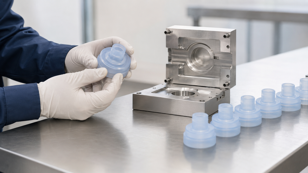
首先,釐清原型的目的
在選擇製程或索取報價之前,請先確定原型必須驗證哪些內容。.
外觀原型
外觀原型會評估:
- 整體形狀
- 尺寸與比例
- 色彩方向
- 表面質地
- 按鈕位置
- 使用者處理
- 組裝空間
該材料不一定非得與生產用的矽膠相同。.
適配與組裝原型
一個合適的原型應具備以下特點:
- 與塑膠或金屬組件的接合
- 孔與軸的對準
- 外殼內的壓縮
- 纜線與連接器的佈線
- 插入位置
- 卡扣式或機械式固定裝置
- 組裝順序
- 間隙與干擾
在現階段,尺寸精度可能比精確的材料性質更為重要。.
功能性原型
功能性原型用於評估:
- 密封性能
- 觸覺力
- 拔出力
- 抗撕裂性
- 閥門開啟壓力
- 流量
- 靈活性
- 電導率
- 黏結強度
- 重複使用時的表現
原型材料與製程越接近量產階段,所得結果就越具實用價值。.
量產級原型機
一款與量產版相當的原型機採用:
- 預定使用的矽膠等級
- 量產用模具
- 相似的成型溫度與壓力
- 定義式固化或後固化
- 預定使用的嵌件或基材
- 生產檢驗方法
- 典型的二次加工工序
在進行試產、可靠性測試或法規驗證之前,通常需要這些樣品。.
在確定最終設計之前,請先選擇矽膠製程
“「矽膠」涵蓋多種材料及成型方法。設計應與預定的生產製程相符。.
液態矽膠射出成型
LSR 以雙組分形式供應,需先進行定量、混合,再注入加熱後的模具中。.
LSR 注塑成型適用於:
- 大批量零件
- 薄牆
- 複雜的細節
- 醫療及嬰幼兒護理相關產品
- 閥門與隔膜
- 密封件與墊片
- 矽膠包覆塑膠成型
- 自動化生產
LSR 的加工黏度較低,且能填補極細微的縫隙,因此精確的分模線與可控的模具結構尤為重要。陶氏的 LSR 加工指南將材料行為、模具設計、溢料、固化及脫模等環節視為相互關聯的製程變數加以探討。(陶氏 LSR 注塑成型指南)
高濃度橡膠成型
HCR 是一種堅硬、類似橡膠的矽膠,可透過以下方式進行加工:
- 壓縮成型
- 轉注成型
- 射出成型
- 擠出
壓縮成型通常適用於:
- 墊片
- 鍵盤
- 簡單的密封件
- 較大的元件
- 小批量零件
- 原型製作與過渡性生產
雖然原型壓縮成型模具可能比全自動 LSR 注塑模具更為簡單,但零件的一致性與飛邊控制仍取決於混合物的配比、壓力、溫度及固化時間。.
RTV 矽膠鑄造
室溫固化矽膠可經混合後,倒入或擠入模具中。.
RTV 鑄造適用於:
- 早期功能性樣品
- 數量極少
- 觸感柔軟的原型
- 大型或簡單的元件
- 硬度評估
- 封裝概念
然而,澆鑄的 RTV 矽膠可能無法精確重現注塑成型 LSR 的特性、收縮率、表面狀態或生產行為。.
增材製造
矽膠 3D 列印與軟質彈性體列印無需傳統模具,即可製成複雜的形狀。.
增材製造原型可能有助於評估:
- 形式與外觀
- 人體工學
- 內部管道
- 設計方案
- 組裝空間
- 早期階段的使用者測試
該印刷品在抗撕裂強度、伸長率、表面光潔度、壓縮永久變形率及耐化學性等方面,可能與模製生產用的矽膠有所不同。不應自動將其視為與量產產品相當的樣品。.
SIMTEC 將增材製造、CNC 加工、鑄造及試產列為不同的原型製作途徑,每種途徑各有其優點與限制。(SIMTEC 原型製程選項)
矽膠設計製造(DFM):關鍵設計考量事項
可製造性設計應在訂購原型模具之前就開始進行。.
1. 材料等級與硬度
該詢價單應明確列出「矽膠」以外的其他項目。“
請指定:
- LSR、HCR 或 RTV
- 岸硬度
- 顏色
- 治療系統
- 透明度
- 抗撕裂強度要求
- 壓縮永久變形要求
- 導電級或絕緣級
- 食品接觸或醫療需求
- 自黏合能力
- 阻燃要求
- 後固化要求
兩種肖氏硬度相同的矽膠等級,在成型、脫模及功能測試過程中,其表現可能有所不同。.
2. 壁厚
矽膠雖能填充薄壁部位,但隨著壁厚變薄,成型與脫模的難度也會隨之增加。.
極薄的區域可能會:
- 脫模時發生撕裂
- 搬運時請摺疊
- 與較厚部位的固化方式不同
- 造成測量上的困難
- 需要額外的模具支撐
- 在包裝或組裝載荷作用下發生變形
極為厚實的部位可能需要更長的固化時間,並可能影響生產週期。.
在可行情況下,應盡量採用漸變效果,而非在粗細部分之間進行突兀的變化。.
3. 分型線位置
在設計製造分析(DFM)過程中,應明確標示模具的分型線,因為它可能會留下可見的分型痕跡或殘留飛邊。.
請避免將分型線設置於:
- 關鍵密封面
- 光學領域
- 與皮膚接觸的邊緣
- 閥門縫隙
- 電氣接觸面
- 黏合區
- 精密組裝介面
若無法移動分型線,則應在圖紙中明確定義允許的飛邊及錯位量。.
4. 閘門位置
澆口控制著矽膠如何流入型腔。.
閘門的位置可能會影響:
- 結餘
- 氣泡困住
- 針織線
- 城門遺跡
- 外觀
- 修剪要求
- 局部應力
- 插件周圍的流場
- 多腔室的一致性
除非幾何形狀有特殊要求,否則閘口通常應設置在遠離關鍵外觀或功能區域的位置。.
5. 發洩情緒
當矽膠填滿空腔時,空氣必須排出。.
通風不良可能導致:
- 短鏡頭
- 殘留空氣
- 表面缺陷
- 不完整的細微特徵
- 薄弱環節
- 不規則填充
通風口必須能夠排出空氣,同時不得成為失控的閃燃通道。.
6. 拉坯與脫模
矽膠的柔韌性雖能讓部分零件在倒角處順利脫模,但這種柔韌性並不能完全消除脫模風險。.
DFM 審查應考量以下事項:
- 底切深度
- 移除時請拉伸
- 易撕角
- 芯長
- 表面質地
- Vacuum retention
- Thin membranes
- 零件方向
- Manual or automated demolding
A part that can be removed once during a tooling trial may still be unsuitable for stable high-volume automation.
7. Radii and Tear Prevention
Sharp internal corners can concentrate stress during demolding and use.
Add suitable radii around:
- Holes
- Slots
- 拉環
- Tethers
- Membrane transitions
- Insert edges
- Cable exits
- Mechanical locking features
The radius should be designed according to wall thickness and available space.
8. Dimensional Tolerances
Silicone parts are flexible and shrink after molding. Applying tight tolerances to every dimension increases tooling and inspection cost without necessarily improving function.
Divide dimensions into:
- Critical functional dimensions
- Assembly dimensions
- Sealing dimensions
- Cosmetic dimensions
- Reference dimensions
The inspection method must also be considered. A conventional caliper can compress a soft silicone part and produce misleading results.
SIMTEC notes that prototype testing with the intended material can help establish realistic shrinkage values before final tool dimensions are fixed. (SIMTEC LSR design guidance)
9. Inserts and Overmolding
For silicone-to-plastic or silicone-to-metal components, provide complete substrate information.
重要因素包括:
- Exact plastic resin or metal grade
- Insert tolerance
- 表面處理
- Coating or plating
- Moisture condition
- 耐熱性
- Insert positioning
- Mechanical locking features
- Primer or plasma treatment
- Self-bonding LSR compatibility
Prototype inserts should be manufactured using a process and material condition representative of production.
10. Surface Finish and Appearance
Define whether the silicone surface should be:
- Polished
- 啞光
- Lightly textured
- Optical
- 透明
- 半透明
- 光面
- Coated
- Printed
- Laser marked
Texture can influence release, appearance, cleaning and bonding. The prototype process may not reproduce the final production texture exactly.
Prototype Tooling Options
1. Cast Prototype Molds
A master pattern is produced using CNC machining or 3D printing. A secondary mold is then used to cast RTV silicone parts.
Best for:
- Very small quantities
- Early design evaluation
- Large soft parts
- Low-cost concept validation
- Multiple design iterations
優點:
- Low initial investment
- Fast design changes
- No injection molding machine required
- Useful for checking form and basic function
限制:
- Limited mold life
- Lower dimensional consistency
- Manual mixing and pouring variation
- Air-bubble risk
- Not always production-grade material
- Different shrinkage from injection molding
- Limited representation of production flash and gate conditions
2. 3D-Printed Prototype Molds
A mold may be printed from a suitable polymer and used for casting or selected low-temperature molding trials.
Best for:
- Early geometry checks
- 數量極少
- Rapid design iterations
- Simple casting trials
限制:
- Limited temperature and pressure resistance
- Surface layers may transfer to the part
- Short tool life
- Potential cure inhibition
- Difficult flash control
- Generally unsuitable for production-equivalent LSR injection molding
Compatibility between the printed mold material and silicone cure system must be tested.
3. Single-Cavity Compression Tooling
A simple metal compression mold can produce prototypes using HCR or suitable silicone compounds.
Best for:
- 墊片
- Plugs
- 鍵盤
- Covers
- Seals
- Simple consumer products
- Small pilot quantities
優點:
- Uses real silicone compounds
- Lower complexity than automated injection tooling
- Supports functional testing
- Can produce representative surface finishes
- Suitable for moderate prototype quantities
限制:
- 更多手動處理
- Greater flash and trimming requirements
- Compound placement can affect consistency
- Cycle time is less representative of automated production
- Difficult for very thin or highly complex geometries
4. Prototype LSR Injection Tooling
A prototype LSR tool may use a single cavity, simplified runner system and standardized mold base.
Best for:
- Functional LSR prototypes
- Thin-walled parts
- 閥門與隔膜
- 醫療元件
- Overmolded assemblies
- Near-production testing
- Pilot runs
優點:
- Uses production-intent LSR
- Provides representative curing and shrinkage
- Supports meaningful leak, force and durability tests
- Produces repeatable parts
- Helps identify production molding risks
限制:
- Higher cost than casting
- Requires LSR molding equipment
- Tool changes take time
- Simplified tooling may not reproduce final automation
- Single-cavity data may not predict multi-cavity balance
5. Aluminum Rapid Tooling
Aluminum is easier to machine than hardened steel and can reduce initial tooling lead time.
Protolabs describes aluminum molds as a rapid route for producing LSR parts during development and approval stages. (Protolabs rapid LSR molding)
Best for:
- Prototype injection molding
- Bridge production
- Moderate part quantities
- 設計驗證
- Early customer samples
優點:
- Faster machining
- Lower initial tooling cost
- Easier modification
- Suitable for many pilot applications
限制:
- Shorter life than hardened production steel
- Greater risk of wear in critical shutoffs
- May not suit very tight flash requirements
- Not ideal for every optical or highly automated part
- Tool life depends heavily on geometry and process
Aluminum tooling capability varies by supplier, part design and silicone process. It should be confirmed before the material is specified.
6. Soft-Steel or Modular Insert Tooling
Machined steel cavity inserts can be installed in a reusable mold base.
Best for:
- Production-intent prototypes
- Parts requiring controlled shutoffs
- Pilot production
- Future design changes
- Projects expected to scale
優點:
- Better wear resistance
- More representative of production tooling
- Replaceable cavity inserts
- Improved flash control
- Supports controlled pilot runs
限制:
- Higher initial cost than basic casting tools
- Longer machining time
- Modifications may be more expensive
- Mold-base compatibility must be planned
7. Full Production Tooling
A production mold may include:
- 多個腔室
- Cold-runner system
- Automated demolding
- Insert loading
- Vision inspection
- In-mold sensors
- Secondary operations
- Robot handling
- Cavity traceability
It provides the lowest unit cost at high volume but requires the highest initial investment and the most complete design validation.
Tooling Comparison
| Tooling Route | Typical Development Stage | Material Accuracy | Repeatability | Relative Investment |
|---|---|---|---|---|
| Cast prototype mold | Concept and early function | Low to medium | 低 | Lowest |
| 3D-printed mold | Early iteration | Low to medium | 低 | 低 |
| Compression prototype tool | Functional prototype | 中至高 | 中 | Low to medium |
| Prototype LSR injection tool | Functional validation | 高 | 高 | 中 |
| Aluminum rapid tool | 原型製作與過渡性生產 | 高 | 高 | 中 |
| Modular steel insert tool | Pilot and scale-up | 高 | 高 | 中至高 |
| Full production tool | Serial production | Highest | Highest | Highest |
Prototype Tooling Should Anticipate Production
A low-cost prototype tool is most valuable when it answers questions that affect production tooling.
Where practical, prototype tooling should evaluate:
- Intended parting line
- Gate location
- Venting strategy
- Demolding direction
- Critical tolerances
- 表面處理
- Insert positioning
- Flash-sensitive areas
- Secondary operations
- Inspection datums
If the prototype uses a completely different gate, parting line or molding process, some results may not transfer to production.
From CAD to Pilot Production
Stage 1: Requirements Review
請確認:
- 應用
- 材料
- 數量
- Critical dimensions
- 機械性能
- Sealing requirements
- 監管要求
- Test conditions
- Production target
Stage 2: DFM Review
The supplier reviews:
- 壁厚
- 分型線
- Gate and vent locations
- 底切
- 脫模
- Flash limits
- Tolerances
- Inserts
- Surface requirements
Design changes should be completed before cutting metal where possible.
Stage 3: Prototype Tooling
The tool is manufactured and inspected. Critical mold dimensions and surfaces are checked before the first trial.
Stage 4: Initial Tool Trial
Initial samples are evaluated for:
- Complete filling
- Flash
- 氣泡困住
- 養護
- 脫模
- 表面狀況
- 尺寸
- 城門遺跡
- 插入位置
The first trial should identify tooling and process issues, not serve as an automatic production approval.
Stage 5: Tool Correction and Second Trial
The mold or process may be adjusted based on initial results.
Changes may include:
- Vent depth
- Gate geometry
- Shutoff surfaces
- Cavity dimensions
- 表面處理
- Insert fixture
- Cure conditions
- Injection settings
Stage 6: First Article Inspection
The first article report should focus on dimensions and functions that affect assembly or performance.
Inspection may include:
- Dimensional report
- 材料驗證
- 硬度
- 顏色
- Visual condition
- Flash
- 重量
- Functional test results
- Insert location
- 黏結強度
- Leak rate
- Force-displacement data
Stage 7: Pilot Production
Pilot production uses a controlled batch to evaluate whether the process can repeatedly produce acceptable parts.
A pilot run should verify:
- Material handling
- Metering and mixing
- 模具溫度
- Injection stability
- 固化時間
- 腔式天平
- 脫模
- Trimming
- 後固化
- 清潔
- Inspection
- 包裝
- 可追溯性
SIMTEC describes pilot production as a way to generate near-production-quality LSR parts and transfer lessons into the final production process. (SIMTEC pilot LSR production)
What Pilot Production Should Prove
A pilot run should answer four questions.
1. Is the Design Functional?
測試可能包括:
- Leakage
- Compression
- 拔出力
- Actuation force
- 流量
- 抗撕裂強度
- 組裝
- Bonding
- Electrical resistance
- 使用者處理
2. Is the Molding Process Stable?
評論:
- Shot-to-shot variation
- Cure consistency
- Flash stability
- Cavity differences
- Material ratio
- 週期時間
- Scrap rate
- Demolding reliability
3. Can the Part Be Inspected Reliably?
請確認:
- Measurement fixtures
- 檢驗方法
- Sampling plan
- Critical dimensions
- Visual standards
- Functional test equipment
- Calibrated reference parts
4. Can the Part Be Manufactured at the Target Cost?
Record:
- 週期時間
- Labor content
- 材料用量
- Scrap
- Trimming time
- Secondary operations
- Inspection time
- 包裝成本
Critical-to-Quality Characteristics
Not every dimension needs extensive pilot data. Focus on characteristics that affect safety, assembly, sealing or customer use.
例如:
- Sealing diameter
- Membrane thickness
- Valve slit
- Insert location
- 黏結強度
- 拔出力
- Actuation force
- Contact resistance
- Leak rate
- 表面污染
- Flash at a critical edge
Capability calculations should only be used when the process is stable and sufficient representative data are available.
Production-Intent Testing
Pilot samples should be tested under expected service conditions.
測試可能包括:
- Temperature aging
- 熱循環
- 濕度
- Chemical exposure
- Water immersion
- 紫外線照射
- 滅菌
- 壓縮永久變形
- 疲勞循環
- Repeated assembly
- Packaging and shipping simulation
Early prototype results should not replace validation using production-intent materials and processes.
Common Prototype Manufacturing Problems
| Problem | Likely Cause | Recommended Action |
| Prototype fits but production part does not | Different material or shrinkage | Use production-grade material and update tool dimensions |
| Part tears during demolding | Sharp corner, deep undercut or thin wall | Add radii or revise demolding direction |
| 過度閃光 | Tool gap, excessive shot or worn shutoff | Review tooling fit and process settings |
| Part is tacky | Insufficient cure or incorrect mixing | Verify temperature, cure time and mix ratio |
| Air bubbles or voids | Poor venting or casting technique | Improve venting, vacuum or filling method |
| Hardness differs from requirement | Incorrect material or cure condition | Confirm grade, mixing and test method |
| Insert moves during molding | Weak fixture or excessive injection force | Improve insert location and support |
| Pilot cycle is too slow | Tool or demolding process is not optimized | Review automation and cure conditions |
| Dimensions vary between samples | Unstable process or measurement deformation | Stabilize molding and use proper fixtures |
| Surface appearance is inconsistent | Tool finish, release or contamination | Standardize mold and handling conditions |
Cost Drivers for Silicone Prototypes
Prototype cost is influenced by:
- Part size
- Geometry complexity
- Number of cavities
- 底切
- 表面處理
- Flash requirement
- 材料等級
- Insert molding
- Self-bonding requirements
- Tool material
- Required quantity
- 寬容
- Secondary operations
- Inspection documents
- 功能測試
- Cleanroom requirements
The cheapest prototype method is not always the most economical choice. A low-fidelity sample that cannot answer the required engineering questions may delay the project and increase the cost of later tooling changes.
Silicone Prototype RFQ Checklist
Provide:
- 2D 圖面
- 3D CAD 檔案
- Prototype purpose
- Required quantity
- Target production volume
- LSR, HCR or RTV preference
- 材料等級
- 岸硬度
- 顏色
- Critical dimensions
- Flash limits
- 表面處理
- Insert or substrate drawings
- 保證金要求
- Functional test requirements
- 環境暴露
- Post-curing requirements
- 監管要求
- Inspection documents
- Target pilot-production date
Also identify whether the prototype must match the final production material and process.
結論
Successful silicone prototyping begins by defining what the prototype must prove.
Early appearance and fit checks may use additive manufacturing or cast silicone. Functional testing often requires real silicone compounds and controlled prototype tooling. Production-equivalent validation typically requires compression molding or LSR injection molding using production-intent materials, gates, parting lines and curing conditions.
A structured DFM review reduces tooling changes by addressing wall thickness, parting lines, gates, vents, tolerances, undercuts, inserts and inspection methods before mold construction. Pilot production then confirms that the design, tooling, molding process, secondary operations and quality controls can operate together consistently.
FHY Silicone supports silicone product DFM, prototype tooling, LSR molding, compression molding, overmolding and pilot production. Send us your CAD files, material requirements, prototype quantity and target production volume for a manufacturability review.
常見問題
Which process is best for a silicone prototype?
It depends on the purpose. Casting or 3D printing may be suitable for appearance and fit, while functional or production-equivalent testing usually requires molded production-grade silicone.
Can a 3D-printed soft part replace an LSR prototype?
Not always. Printed elastomers may differ from LSR in tear strength, elongation, compression set, surface finish and chemical resistance.
Is prototype tooling always discarded?
No. Aluminum or modular insert tooling may sometimes support pilot or bridge production. Tool life and future use should be agreed before manufacturing.
Should the prototype use the final production material?
Use the production material when testing sealing, bonding, chemical resistance, sterilization, compression set or long-term mechanical performance.
What is pilot production?
Pilot production is a controlled pre-production batch used to verify process stability, part quality, inspection methods, secondary operations and packaging before serial manufacturing.
How many parts are needed for a pilot run?
There is no universal quantity. It depends on process complexity, testing requirements, number of cavities and the amount of data needed to evaluate repeatability.
What is the difference between a prototype tool and a production tool?
Prototype tooling usually emphasizes speed, lower cost and design flexibility. Production tooling emphasizes long life, automation, multiple cavities and consistent high-volume output.
Can prototype samples be used for regulatory testing?
Only when the material, tooling, manufacturing process and documentation meet the project’s validation requirements. This should be confirmed with the customer’s regulatory and quality teams.
 English
  Japanese
  Korean
  German
  French
  Italian
  Spanish
  Dutch
Dutch  Chinese
  Portuguese
  Polish
  Czech
Czech  Hungarian
  Swedish
  Finnish
  Vietnamese
  Thai
Thai  Turkish
  Arabic
  Russian