
Silicone prototyping is not simply about producing a soft part that looks like the final product. A useful prototype must answer specific engineering questions: Does the geometry assemble correctly? Does the material provide the required flexibility? Can the part seal, bond, stretch or withstand repeated use? Can the design be molded consistently at production volume?
The right prototyping method depends on the development stage. A 3D-printed elastomer may be suitable for checking shape and ergonomics, while functional testing may require the actual production silicone. Final validation and pilot production normally require a production-intent molding process.
This guide explains silicone design for manufacturability, prototype tooling options and the steps required to move from early samples to controlled pilot production.
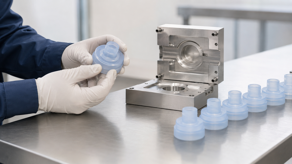
Start by Defining the Purpose of the Prototype
Before selecting a process or requesting a quotation, determine what the prototype must prove.
Appearance Prototype
An appearance prototype evaluates:
- Overall shape
- Size and proportions
- Color direction
- Oberflächenstruktur
- Button position
- User handling
- Assembly space
The material does not always need to match production silicone.
Fit and Assembly Prototype
A fit prototype checks:
- Interface with plastic or metal components
- Hole and shaft alignment
- Compression in a housing
- Cable and connector routing
- Einfügeposition
- Snap or mechanical retention
- Assembly sequence
- Clearance and interference
Dimensional accuracy may be more important than exact material properties at this stage.
Functional Prototype
A functional prototype evaluates:
- Dichtungsleistung
- Tactile force
- Pull-out force
- Reißfestigkeit
- Valve opening pressure
- Durchflussmenge
- Flexibilität
- Elektrische Leitfähigkeit
- Haftfestigkeit
- Repeated-use performance
The closer the prototype material and process are to production, the more useful the results will be.
Production-Equivalent Prototype
A production-equivalent prototype uses:
- The intended silicone grade
- Production-intent tooling
- Similar molding temperature and pressure
- Defined curing or post-curing
- Intended inserts or substrates
- Production inspection methods
- Representative secondary operations
These samples are often required before pilot production, reliability testing or regulatory validation.
Choose the Silicone Process Before Finalizing the Design
“Silicone” covers several materials and molding methods. The design should match the intended production process.
Liquid Silicone Rubber Injection Molding
LSR is supplied as two components that are metered, mixed and injected into a heated mold.
Das LSR-Spritzgießen eignet sich für:
- High-volume parts
- Thin walls
- Complex details
- Medical and baby-care components
- Valves and membranes
- Dichtungen und Dichtringe
- Silicone-to-plastic overmolding
- Automatisierte Fertigung
LSR has low processing viscosity and can fill very small gaps, which makes precise parting lines and controlled mold construction especially important. Dow’s LSR processing guide covers material behavior, mold design, flashing, curing and demolding as connected process variables. (Dow LSR injection molding guide)
High-Consistency Rubber Molding
HCR is a solid, gum-like silicone that may be processed by:
- Formpressen
- Transferformverfahren
- Spritzguss
- Extrusion
Das Formpressen eignet sich häufig für:
- Dichtungen
- Tastaturen
- Simple seals
- Larger components
- Lower-volume parts
- Prototype and bridge production
Prototype compression tooling may be simpler than a fully automated LSR injection mold, but part consistency and flash control still depend on compound placement, pressure, temperature and cure time.
RTV Silicone Casting
Room-temperature-vulcanizing silicone can be mixed and poured or dispensed into a mold.
RTV casting is useful for:
- Early functional samples
- Very low quantities
- Soft-touch prototypes
- Large or simple components
- Evaluating hardness
- Encapsulation concepts
However, cast RTV silicone may not reproduce the exact properties, shrinkage, surface condition or production behavior of injection-molded LSR.
Additive Manufacturing
Silicone 3D printing and soft elastomer printing can produce complex shapes without conventional tooling.
Additive prototypes may help evaluate:
- Form and appearance
- Ergonomie
- Internal channels
- Design alternatives
- Assembly space
- Early-stage user testing
The printed material may have different tear strength, elongation, surface finish, compression set and chemical resistance from molded production silicone. It should not automatically be treated as a production-equivalent sample.
SIMTEC lists additive manufacturing, CNC machining, casting and pilot pre-production as different prototype routes, each with its own advantages and limitations. (SIMTEC prototype process options)
Silicone DFM: Key Design Considerations
Design for manufacturability should begin before prototype tooling is ordered.
1. Material Grade and Hardness
The RFQ should identify more than “silicone rubber.”
Geben Sie Folgendes an:
- LSR, HCR or RTV
- Shore hardness
- Farbe
- Aushärtungssystem
- Transparenz
- Tear-strength requirement
- Compression-set requirement
- Conductive or insulating grade
- Food-contact or medical requirement
- Self-bonding capability
- Flame-retardant requirement
- Anforderungen an die Nachhärtung
Two silicone grades with the same Shore hardness may behave differently during molding, demolding and functional testing.
2. Wall Thickness
Silicone can fill thin sections, but molding and demolding become more difficult as walls become thinner.
Very thin areas may:
- Riss beim Entformen
- Fold during handling
- Cure differently from thick areas
- Create measurement difficulties
- Require additional mold support
- Deform under packaging or assembly loads
Extremely thick areas may require longer cure time and can affect production cycle time.
Use gradual transitions where possible instead of abrupt changes between thick and thin sections.
3. Parting-Line Position
The mold parting line should be identified during DFM because it can leave a visible witness line or residual flash.
Avoid placing the parting line on:
- Critical sealing lands
- Optical areas
- Skin-contact edges
- Valve slits
- Electrical contact surfaces
- Adhesive bonding zones
- Precision assembly interfaces
If the parting line cannot be moved, the drawing should define the permitted flash and mismatch.
4. Gate Position
The gate controls how silicone enters the cavity.
Gate location can affect:
- Filling balance
- Luftansammlung
- Knit lines
- Gate vestige
- Cosmetic appearance
- Trim requirements
- Local stress
- Flow around inserts
- Multi-cavity consistency
The gate should normally be located away from critical cosmetic or functional areas unless the geometry requires otherwise.
5. Venting
Air must escape as silicone fills the cavity.
Eine unzureichende Belüftung kann folgende Folgen haben:
- Kurzschüsse
- Eingeschlossene Luft
- Oberflächenfehler
- Incomplete thin features
- Weak areas
- Irregular filling
Vents must release air without becoming uncontrolled flash paths.
6. Draft and Demolding
Silicone flexibility allows some parts to demold around undercuts, but flexibility does not eliminate demolding risk.
The DFM review should consider:
- Undercut depth
- Stretch during removal
- Tear-sensitive corners
- Core length
- Oberflächenstruktur
- Vacuum retention
- Dünne Membranen
- Part orientation
- Manual or automated demolding
A part that can be removed once during a tooling trial may still be unsuitable for stable high-volume automation.
7. Radii and Tear Prevention
Sharp internal corners can concentrate stress during demolding and use.
Add suitable radii around:
- Löcher
- Spielautomaten
- Aufreißlaschen
- Tethers
- Membrane transitions
- Kanten einfügen
- Kabelausgänge
- Mechanical locking features
The radius should be designed according to wall thickness and available space.
8. Dimensional Tolerances
Silicone parts are flexible and shrink after molding. Applying tight tolerances to every dimension increases tooling and inspection cost without necessarily improving function.
Divide dimensions into:
- Critical functional dimensions
- Assembly dimensions
- Sealing dimensions
- Cosmetic dimensions
- Reference dimensions
The inspection method must also be considered. A conventional caliper can compress a soft silicone part and produce misleading results.
SIMTEC notes that prototype testing with the intended material can help establish realistic shrinkage values before final tool dimensions are fixed. (SIMTEC LSR design guidance)
9. Inserts and Overmolding
For silicone-to-plastic or silicone-to-metal components, provide complete substrate information.
Zu den wichtigen Faktoren zählen:
- Exact plastic resin or metal grade
- Insert tolerance
- Oberflächenbeschaffenheit
- Coating or plating
- Moisture condition
- Hitzebeständigkeit
- Positionierung des Einsatzes
- Mechanical locking features
- Primer or plasma treatment
- Self-bonding LSR compatibility
Prototype inserts should be manufactured using a process and material condition representative of production.
10. Surface Finish and Appearance
Define whether the silicone surface should be:
- Polished
- Matt
- Lightly textured
- Optical
- Transparent
- Durchscheinend
- Glänzend
- Coated
- Printed
- Laser marked
Texture can influence release, appearance, cleaning and bonding. The prototype process may not reproduce the final production texture exactly.
Prototype Tooling Options
1. Cast Prototype Molds
A master pattern is produced using CNC machining or 3D printing. A secondary mold is then used to cast RTV silicone parts.
Best for:
- Very small quantities
- Early design evaluation
- Large soft parts
- Low-cost concept validation
- Multiple design iterations
Vorteile:
- Low initial investment
- Fast design changes
- No injection molding machine required
- Useful for checking form and basic function
Einschränkungen:
- Limited mold life
- Lower dimensional consistency
- Manual mixing and pouring variation
- Air-bubble risk
- Not always production-grade material
- Different shrinkage from injection molding
- Limited representation of production flash and gate conditions
2. 3D-Printed Prototype Molds
A mold may be printed from a suitable polymer and used for casting or selected low-temperature molding trials.
Best for:
- Early geometry checks
- Very low quantities
- Rapid design iterations
- Simple casting trials
Einschränkungen:
- Limited temperature and pressure resistance
- Surface layers may transfer to the part
- Short tool life
- Potential cure inhibition
- Difficult flash control
- Generally unsuitable for production-equivalent LSR injection molding
Compatibility between the printed mold material and silicone cure system must be tested.
3. Single-Cavity Compression Tooling
A simple metal compression mold can produce prototypes using HCR or suitable silicone compounds.
Best for:
- Dichtungen
- Plugs
- Tastaturen
- Umschläge
- Seals
- Simple consumer products
- Small pilot quantities
Vorteile:
- Uses real silicone compounds
- Lower complexity than automated injection tooling
- Supports functional testing
- Can produce representative surface finishes
- Suitable for moderate prototype quantities
Einschränkungen:
- Mehr manuelle Bearbeitung
- Greater flash and trimming requirements
- Compound placement can affect consistency
- Cycle time is less representative of automated production
- Difficult for very thin or highly complex geometries
4. Prototype LSR Injection Tooling
A prototype LSR tool may use a single cavity, simplified runner system and standardized mold base.
Best for:
- Functional LSR prototypes
- Thin-walled parts
- Valves and membranes
- Medizinische Komponenten
- Overmolded assemblies
- Near-production testing
- Pilot runs
Vorteile:
- Uses production-intent LSR
- Provides representative curing and shrinkage
- Supports meaningful leak, force and durability tests
- Produces repeatable parts
- Helps identify production molding risks
Einschränkungen:
- Higher cost than casting
- Requires LSR molding equipment
- Tool changes take time
- Simplified tooling may not reproduce final automation
- Single-cavity data may not predict multi-cavity balance
5. Aluminum Rapid Tooling
Aluminum is easier to machine than hardened steel and can reduce initial tooling lead time.
Protolabs describes aluminum molds as a rapid route for producing LSR parts during development and approval stages. (Protolabs rapid LSR molding)
Best for:
- Prototype injection molding
- Bridge production
- Moderate part quantities
- Designvalidierung
- Early customer samples
Vorteile:
- Faster machining
- Geringere anfängliche Werkzeugkosten
- Easier modification
- Suitable for many pilot applications
Einschränkungen:
- Shorter life than hardened production steel
- Greater risk of wear in critical shutoffs
- May not suit very tight flash requirements
- Not ideal for every optical or highly automated part
- Tool life depends heavily on geometry and process
Aluminum tooling capability varies by supplier, part design and silicone process. It should be confirmed before the material is specified.
6. Soft-Steel or Modular Insert Tooling
Machined steel cavity inserts can be installed in a reusable mold base.
Best for:
- Production-intent prototypes
- Parts requiring controlled shutoffs
- Pilot production
- Future design changes
- Projects expected to scale
Vorteile:
- Better wear resistance
- More representative of production tooling
- Replaceable cavity inserts
- Improved flash control
- Supports controlled pilot runs
Einschränkungen:
- Higher initial cost than basic casting tools
- Longer machining time
- Modifications may be more expensive
- Mold-base compatibility must be planned
7. Full Production Tooling
A production mold may include:
- Mehrere Hohlräume
- Cold-runner system
- Automated demolding
- Ladevorgang läuft
- Optische Prüfung
- In-mold sensors
- Sekundäre Arbeitsgänge
- Robot handling
- Cavity traceability
It provides the lowest unit cost at high volume but requires the highest initial investment and the most complete design validation.
Tooling Comparison
| Tooling Route | Typical Development Stage | Material Accuracy | Repeatability | Relative Investment |
|---|---|---|---|---|
| Cast prototype mold | Concept and early function | Low to medium | Niedrig | Lowest |
| 3D-printed mold | Early iteration | Low to medium | Niedrig | Niedrig |
| Compression prototype tool | Functional prototype | Medium to high | Mittel | Low to medium |
| Prototype LSR injection tool | Functional validation | Hoch | Hoch | Mittel |
| Aluminum rapid tool | Prototype and bridge production | Hoch | Hoch | Mittel |
| Modular steel insert tool | Pilot and scale-up | Hoch | Hoch | Medium to high |
| Full production tool | Serial production | Highest | Highest | Highest |
Prototype Tooling Should Anticipate Production
A low-cost prototype tool is most valuable when it answers questions that affect production tooling.
Where practical, prototype tooling should evaluate:
- Intended parting line
- Standort des Tors
- Venting strategy
- Demolding direction
- Kritische Toleranzen
- Oberflächenbeschaffenheit
- Positionierung des Einsatzes
- Flash-sensitive areas
- Sekundäre Arbeitsgänge
- Inspection datums
If the prototype uses a completely different gate, parting line or molding process, some results may not transfer to production.
From CAD to Pilot Production
Stage 1: Requirements Review
Bestätigen:
- Anwendung
- Material
- Anzahl
- Kritische Abmessungen
- Mechanische Leistung
- Sealing requirements
- Gesetzliche Anforderungen
- Test conditions
- Production target
Stage 2: DFM Review
The supplier reviews:
- Wandstärke
- Trennlinie
- Gate and vent locations
- Unterschnitte
- Entformen
- Flash limits
- Tolerances
- Beilagen
- Surface requirements
Design changes should be completed before cutting metal where possible.
Stage 3: Prototype Tooling
The tool is manufactured and inspected. Critical mold dimensions and surfaces are checked before the first trial.
Stage 4: Initial Tool Trial
Initial samples are evaluated for:
- Complete filling
- Flash
- Luftansammlung
- Aushärten
- Entformen
- Oberflächenbeschaffenheit
- Abmessungen
- Gate vestige
- Einfügeposition
The first trial should identify tooling and process issues, not serve as an automatic production approval.
Stage 5: Tool Correction and Second Trial
The mold or process may be adjusted based on initial results.
Changes may include:
- Vent depth
- Gate geometry
- Shutoff surfaces
- Cavity dimensions
- Oberflächenbeschaffenheit
- Insert fixture
- Heilungsbedingungen
- Injektionseinstellungen
Stage 6: First Article Inspection
The first article report should focus on dimensions and functions that affect assembly or performance.
Inspection may include:
- Dimensional report
- Materialprüfung
- Härte
- Farbe
- Visual condition
- Flash
- Gewicht
- Functional test results
- Einfügeposition
- Haftfestigkeit
- Leak rate
- Force-displacement data
Stage 7: Pilot Production
Pilot production uses a controlled batch to evaluate whether the process can repeatedly produce acceptable parts.
A pilot run should verify:
- Materialtransport
- Metering and mixing
- Formtemperatur
- Injection stability
- Aushärtungszeit
- Hohlraumwaage
- Entformen
- Zuschneiden
- Nachhärtung
- Reinigung
- Prüfung
- Verpackung
- Rückverfolgbarkeit
SIMTEC describes pilot production as a way to generate near-production-quality LSR parts and transfer lessons into the final production process. (SIMTEC pilot LSR production)
What Pilot Production Should Prove
A pilot run should answer four questions.
1. Is the Design Functional?
Die Tests können Folgendes umfassen:
- Leckage
- Compression
- Pull-out force
- Actuation force
- Durchflussmenge
- Reißfestigkeit
- Montage
- Verklebung
- Electrical resistance
- User handling
2. Is the Molding Process Stable?
Rezension:
- Shot-to-shot variation
- Cure consistency
- Flash stability
- Cavity differences
- Material ratio
- Zykluszeit
- Scrap rate
- Demolding reliability
3. Can the Part Be Inspected Reliably?
Bestätigen:
- Measurement fixtures
- Prüfverfahren
- Sampling plan
- Kritische Abmessungen
- Visual standards
- Functional test equipment
- Calibrated reference parts
4. Can the Part Be Manufactured at the Target Cost?
Eintrag:
- Zykluszeit
- Labor content
- Materialverbrauch
- Schrott
- Trimming time
- Sekundäre Arbeitsgänge
- Prüfzeit
- Verpackungskosten
Critical-to-Quality Characteristics
Not every dimension needs extensive pilot data. Focus on characteristics that affect safety, assembly, sealing or customer use.
Beispiele hierfür sind:
- Sealing diameter
- Membrandicke
- Valve slit
- Einfügeposition
- Haftfestigkeit
- Pull-out force
- Actuation force
- Kontaktwiderstand
- Leak rate
- Oberflächenverunreinigung
- Flash at a critical edge
Capability calculations should only be used when the process is stable and sufficient representative data are available.
Production-Intent Testing
Pilot samples should be tested under expected service conditions.
Die Tests können Folgendes umfassen:
- Temperature aging
- Temperaturwechselbeanspruchung
- Luftfeuchtigkeit
- Exposition gegenüber Chemikalien
- Eintauchen in Wasser
- UV-Belastung
- Sterilisation
- Druckverformungsrest
- Wechselbeanspruchung
- Wiederholte Montage
- Packaging and shipping simulation
Early prototype results should not replace validation using production-intent materials and processes.
Common Prototype Manufacturing Problems
| Problem | Likely Cause | Recommended Action |
| Prototype fits but production part does not | Different material or shrinkage | Use production-grade material and update tool dimensions |
| Part tears during demolding | Sharp corner, deep undercut or thin wall | Add radii or revise demolding direction |
| Übermäßiger Blitz | Tool gap, excessive shot or worn shutoff | Review tooling fit and process settings |
| Part is tacky | Insufficient cure or incorrect mixing | Verify temperature, cure time and mix ratio |
| Air bubbles or voids | Poor venting or casting technique | Improve venting, vacuum or filling method |
| Hardness differs from requirement | Incorrect material or cure condition | Confirm grade, mixing and test method |
| Einfügen von Bewegungen während des Formvorgangs | Weak fixture or excessive injection force | Improve insert location and support |
| Pilot cycle is too slow | Tool or demolding process is not optimized | Review automation and cure conditions |
| Dimensions vary between samples | Unstable process or measurement deformation | Stabilize molding and use proper fixtures |
| Surface appearance is inconsistent | Tool finish, release or contamination | Standardize mold and handling conditions |
Cost Drivers for Silicone Prototypes
Prototype cost is influenced by:
- Part size
- Geometry complexity
- Anzahl der Kavitäten
- Unterschnitte
- Oberflächenbeschaffenheit
- Flash requirement
- Werkstoffgüte
- Einschlussformen
- Self-bonding requirements
- Tool material
- Required quantity
- Toleranz
- Sekundäre Arbeitsgänge
- Inspection documents
- Funktionsprüfung
- Reinraumanforderungen
The cheapest prototype method is not always the most economical choice. A low-fidelity sample that cannot answer the required engineering questions may delay the project and increase the cost of later tooling changes.
Silicone Prototype RFQ Checklist
Provide:
- 2D-Zeichnung
- 3D-CAD-Datei
- Prototype purpose
- Required quantity
- Target production volume
- LSR, HCR or RTV preference
- Werkstoffgüte
- Shore hardness
- Farbe
- Kritische Abmessungen
- Flash limits
- Oberflächenbeschaffenheit
- Insert or substrate drawings
- Anforderungen an die Verklebung
- Functional test requirements
- Umwelteinflüsse
- Post-curing requirements
- Gesetzliche Anforderungen
- Inspection documents
- Target pilot-production date
Also identify whether the prototype must match the final production material and process.
Fazit
Successful silicone prototyping begins by defining what the prototype must prove.
Early appearance and fit checks may use additive manufacturing or cast silicone. Functional testing often requires real silicone compounds and controlled prototype tooling. Production-equivalent validation typically requires compression molding or LSR injection molding using production-intent materials, gates, parting lines and curing conditions.
A structured DFM review reduces tooling changes by addressing wall thickness, parting lines, gates, vents, tolerances, undercuts, inserts and inspection methods before mold construction. Pilot production then confirms that the design, tooling, molding process, secondary operations and quality controls can operate together consistently.
FHY Silicone supports silicone product DFM, prototype tooling, LSR molding, compression molding, overmolding and pilot production. Send us your CAD files, material requirements, prototype quantity and target production volume for a manufacturability review.
Häufig gestellte Fragen
Which process is best for a silicone prototype?
It depends on the purpose. Casting or 3D printing may be suitable for appearance and fit, while functional or production-equivalent testing usually requires molded production-grade silicone.
Can a 3D-printed soft part replace an LSR prototype?
Not always. Printed elastomers may differ from LSR in tear strength, elongation, compression set, surface finish and chemical resistance.
Is prototype tooling always discarded?
No. Aluminum or modular insert tooling may sometimes support pilot or bridge production. Tool life and future use should be agreed before manufacturing.
Should the prototype use the final production material?
Use the production material when testing sealing, bonding, chemical resistance, sterilization, compression set or long-term mechanical performance.
What is pilot production?
Pilot production is a controlled pre-production batch used to verify process stability, part quality, inspection methods, secondary operations and packaging before serial manufacturing.
How many parts are needed for a pilot run?
There is no universal quantity. It depends on process complexity, testing requirements, number of cavities and the amount of data needed to evaluate repeatability.
What is the difference between a prototype tool and a production tool?
Prototype tooling usually emphasizes speed, lower cost and design flexibility. Production tooling emphasizes long life, automation, multiple cavities and consistent high-volume output.
Can prototype samples be used for regulatory testing?
Only when the material, tooling, manufacturing process and documentation meet the project’s validation requirements. This should be confirmed with the customer’s regulatory and quality teams.
 English
  Japanese
  Korean
  German
  French
  Italian
  Spanish
  Dutch
Dutch  Chinese
  Portuguese
  Polish
  Czech
Czech  Hungarian
  Swedish
  Finnish
  Vietnamese
  Thai
Thai  Turkish
  Arabic
  Russian