
Silikon prototip üretimi, sadece nihai ürüne benzeyen yumuşak bir parça üretmekten ibaret değildir. Yararlı bir prototip, belirli mühendislik sorularına yanıt vermelidir: Geometri doğru şekilde bir araya geliyor mu? Malzeme gerekli esnekliği sağlıyor mu? Parça sızdırmazlık sağlayabiliyor, yapışabiliyor, esneyebiliyor veya tekrarlı kullanıma dayanabiliyor mu? Tasarım, üretim hacminde tutarlı bir şekilde kalıplanabiliyor mu?
En uygun prototip oluşturma yöntemi, geliştirme aşamasına bağlıdır. Şekil ve ergonomiyi kontrol etmek için 3D baskılı bir elastomer uygun olabilirken, işlevsel testler için gerçek üretim silikonu gerekebilir. Nihai doğrulama ve pilot üretim için genellikle üretim amaçlı kalıplama süreci gereklidir.
Bu kılavuzda, üretilebilirlik açısından silikon tasarımı, prototip kalıplama seçenekleri ve ilk numunelerden kontrollü pilot üretime geçmek için gerekli adımlar açıklanmaktadır.
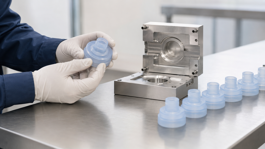
Öncelikle prototipin amacını belirleyin
Bir süreç seçmeden veya fiyat teklifi talep etmeden önce, prototipin neyi kanıtlaması gerektiğini belirleyin.
Görünüm Prototipi
Bir görünüm prototipi şunları değerlendirir:
- Genel şekil
- Boyut ve oranlar
- Renk yönü
- Yüzey dokusu
- Düğme konumu
- Kullanıcı yönetimi
- Montaj alanı
Malzemenin her zaman üretim silikonuyla aynı olması gerekmez.
Uyum ve Montaj Prototipi
Uygun bir prototip şu hususları kontrol eder:
- Plastik veya metal bileşenlerle arayüz
- Delik ve şaft hizalaması
- Bir muhafaza içindeki sıkıştırma
- Kablo ve konektörlerin yönlendirilmesi
- Ekleme konumu
- Kırılma veya mekanik tutunma
- Montaj sırası
- Boşluk ve parazit
Bu aşamada, boyutsal doğruluk, malzemenin kesin özelliklerinden daha önemli olabilir.
İşlevsel Prototip
İşlevsel bir prototip aşağıdakileri değerlendirir:
- Sızdırmazlık performansı
- Dokunsal kuvvet
- Çekme kuvveti
- Yırtılma direnci
- Valf açılma basıncı
- Akış hızı
- Esneklik
- Elektriksel iletkenlik
- Yapışma mukavemeti
- Tekrarlı kullanım performansı
Prototip malzemesi ve süreci üretime ne kadar yakın olursa, sonuçlar o kadar yararlı olacaktır.
Üretimle Eşdeğer Prototip
Üretimle eşdeğer bir prototipte şunlar kullanılır:
- İstenen silikon sınıfı
- Üretim amaçlı kalıplar
- Benzer kalıplama sıcaklığı ve basıncı
- Tanımlanmış kürleme veya sonradan kürleme
- Kullanılması amaçlanan ekler veya alt tabakalar
- Üretim denetim yöntemleri
- Temsili ikincil işlemler
Bu numuneler genellikle pilot üretim, güvenilirlik testleri veya mevzuata uygunluk doğrulaması öncesinde talep edilir.
Tasarımı Son Haline Getirmeden Önce Silikon Üretim Yöntemini Seçin
“Silikon” terimi, çeşitli malzemeleri ve kalıplama yöntemlerini kapsar. Tasarım, hedeflenen üretim sürecine uygun olmalıdır.
Sıvı Silikon Kauçuk Enjeksiyon Kalıplama
LSR, iki bileşen halinde tedarik edilir; bu bileşenler ölçülür, karıştırılır ve ısıtılmış bir kalıba enjekte edilir.
LSR enjeksiyon kalıplama şu alanlar için uygundur:
- Yüksek hacimli parçalar
- İnce duvarlar
- Karmaşık ayrıntılar
- Tıbbi ve bebek bakımı ürünleri
- Valfler ve membranlar
- Contalar ve contalar
- Silikondan plastiğe kaplama
- Otomatik üretim
LSR, işleme viskozitesi düşük bir malzemedir ve çok küçük boşlukları doldurabilir; bu nedenle hassas ayırma çizgileri ve kontrollü kalıp yapımı özellikle önemlidir. Dow’un LSR işleme kılavuzu, malzeme davranışı, kalıp tasarımı, taşma, kürleme ve kalıptan çıkarma süreçlerini birbiriyle bağlantılı süreç değişkenleri olarak ele almaktadır. (Dow LSR enjeksiyon kalıplama kılavuzu)
Yüksek Kıvamlı Kauçuk Kalıplama
HCR, aşağıdaki yöntemlerle işlenebilen katı, sakız kıvamında bir silikondur:
- Pres kalıplama
- Transfer kalıplama
- Enjeksiyon kalıplama
- Ekstrüzyon
Pres kalıplama genellikle aşağıdaki durumlar için uygundur:
- Contalar
- Tuş takımları
- Basit contalar
- Daha büyük bileşenler
- Düşük hacimli parçalar
- Prototip ve ara üretim
Prototip sıkıştırma kalıpları, tam otomatik bir LSR enjeksiyon kalıbından daha basit olabilir; ancak parça tutarlılığı ve çapak kontrolü yine de bileşik yerleştirme, basınç, sıcaklık ve kürlenme süresine bağlıdır.
RTV Silikon Kalıplama
Oda sıcaklığında vulkanize olan silikon karıştırıldıktan sonra bir kalıba dökülebilir veya kalıba sıkılabilir.
RTV döküm yöntemi şu durumlarda kullanışlıdır:
- İlk işlevsel prototipler
- Çok az miktarlar
- Yumuşak dokunuşlu prototipler
- Büyük veya basit bileşenler
- Sertliğin değerlendirilmesi
- Kapsülleme kavramları
Bununla birlikte, döküm RTV silikon, enjeksiyon kalıplama yöntemiyle üretilen LSR’nin özelliklerini, büzülmesini, yüzey durumunu veya üretim davranışını tam olarak yansıtmayabilir.
Katmanlı Üretim
Silikon 3D baskı ve yumuşak elastomer baskı, geleneksel kalıplara gerek kalmadan karmaşık şekiller üretilebilir.
Katmanlı üretim prototipleri aşağıdakilerin değerlendirilmesine yardımcı olabilir:
- Biçim ve görünüm
- Ergonomi
- İç kanallar
- Tasarım seçenekleri
- Montaj alanı
- Erken aşama kullanıcı testleri
Baskılı malzeme, kalıplı üretim silikonundan farklı yırtılma mukavemeti, uzama, yüzey kalitesi, sıkıştırma kalıcılığı ve kimyasal dirence sahip olabilir. Bu malzeme, otomatik olarak üretimle eşdeğer bir numune olarak değerlendirilmemelidir.
SIMTEC, katmanlı üretim, CNC işleme, döküm ve pilot ön üretim yöntemlerini, her birinin kendine özgü avantajları ve sınırlamaları olan farklı prototip üretim yöntemleri olarak sıralamaktadır. (SIMTEC prototip üretim seçenekleri)
Silikon DFM: Temel Tasarım Hususları
Üretilebilirlik tasarımı, prototip kalıplarının siparişi verilmeden önce başlamalıdır.
1. Malzeme Sınıfı ve Sertlik
Teklif Talebi belgesinde, “silikon kauçuk”tan daha ayrıntılı bir tanım yer almalıdır.”
Aşağıdakileri belirtin:
- LSR, HCR veya RTV
- Kıyı sertliği
- Renk
- Tedavi sistemi
- Şeffaflık
- Yırtılma mukavemeti şartı
- Sıkıştırma kalıcılığı şartı
- İletken veya yalıtkan sınıfı
- Gıda ile temas veya tıbbi gereklilik
- Kendiliğinden yapışabilme özelliği
- Alev geciktirici gerekliliği
- Son kürleme gerekliliği
Aynı Shore sertliğine sahip iki farklı silikon türü, kalıplama, kalıptan çıkarma ve işlevsel testler sırasında farklı davranışlar sergileyebilir.
2. Duvar Kalınlığı
Silikon ince kesitleri doldurabilir, ancak duvarlar inceldikçe kalıplama ve kalıptan çıkarma işlemleri daha zor hale gelir.
Çok ince bölgelerde şunlar görülebilir:
- Kalıptan çıkarma sırasında yırtılma
- Taşıma sırasında katlayın
- Kalın bölgelerden farklı şekilde tedavi edin
- Ölçüm zorlukları yaratmak
- Ek kalıp desteği gerektirir
- Ambalajlama veya montaj yükleri altında şekil bozulması
Son derece kalın bölgeler daha uzun kürlenme süresi gerektirebilir ve üretim döngüsü süresini etkileyebilir.
Kalın ve ince bölümler arasında ani değişiklikler yerine, mümkün olduğunca kademeli geçişler kullanın.
3. Kalıp Ayrım Hattının Konumu
Kalıp ayrım çizgisi, DFM aşamasında tespit edilmelidir; zira bu çizgi, gözle görülür bir iz veya kalıntı çapak bırakabilir.
Ayrım çizgisini aşağıdaki yerlere yerleştirmeyin:
- Kritik sızdırmazlık yüzeyleri
- Optik alanlar
- Cilde temas eden kenarlar
- Valf yarıkları
- Elektriksel temas yüzeyleri
- Yapıştırma bölgeleri
- Hassas montaj arayüzleri
Ayrılma çizgisi değiştirilemiyorsa, çizimde izin verilen taşma ve uyumsuzluk değerleri belirtilmelidir.
4. Kapı Konumu
Kapak, silikonun boşluğa nasıl gireceğini kontrol eder.
Kapının konumu şu unsurları etkileyebilir:
- Doldurma dengesi
- Hava sıkışması
- Örgü çizgileri
- Kapı kalıntısı
- Estetik görünüm
- Kesim gereklilikleri
- Yerel gerilim
- Ek parçaların etrafındaki akış
- Çoklu boşluk tutarlılığı
Geometri aksini gerektirmedikçe, kapı normalde kritik estetik veya işlevsel alanlardan uzakta konumlandırılmalıdır.
5. Havalandırma
Silikon boşluğu doldururken havanın dışarı çıkması gerekir.
Yetersiz havalandırma şu sorunlara yol açabilir:
- Kısa çekimler
- Hapsolmuş hava
- Yüzey kusurları
- Eksik ince özellikler
- Zayıf noktalar
- Düzensiz dolgu
Havalandırma delikleri, kontrolsüz alev yayılma yolları haline gelmeden havayı tahliye etmelidir.
6. Çekme ve Kalıptan Çıkarma
Silikonun esnekliği, bazı parçaların alt kesimlerin çevresinden kalıptan çıkmasına olanak sağlar; ancak bu esneklik, kalıptan çıkma riskini ortadan kaldırmaz.
DFM incelemesinde aşağıdaki hususlar dikkate alınmalıdır:
- Alt kesim derinliği
- Çıkarırken esnetin
- Yırtılmaya karşı hassas köşeler
- Çekirdek uzunluğu
- Yüzey dokusu
- Vakum tutma
- İnce zarlar
- Parça yönlendirme
- Manuel veya otomatik kalıptan çıkarma
Bir kalıp denemesi sırasında bir kez çıkarılabilen bir parça, istikrarlı ve yüksek hacimli otomasyon için yine de uygun olmayabilir.
7. Yarıçaplar ve Yırtılmanın Önlenmesi
Keskin iç köşeler, kalıptan çıkarma ve kullanım sırasında gerilimi yoğunlaştırabilir.
Aşağıdakilerin çevresine uygun yarıçaplar ekleyin:
- Delikler
- Slotlar
- Çekme tırnakları
- Bağlantı kordonları
- Membran geçişleri
- Kenarları ekle
- Kablo çıkışları
- Mekanik kilitleme özellikleri
Yarıçap, duvar kalınlığına ve mevcut alana göre belirlenmelidir.
8. Boyutsal Toleranslar
Silikon parçalar esnektir ve kalıplama sonrasında büzülür. Her boyuta sıkı toleranslar uygulamak, işlevselliği mutlaka iyileştirmeden kalıp ve denetim maliyetlerini artırır.
Boyutları şu şekilde ayırın:
- Önemli işlevsel boyutlar
- Montaj boyutları
- Sızdırmazlık boyutları
- Estetik boyutlar
- Referans boyutlar
Denetim yöntemi de göz önünde bulundurulmalıdır. Geleneksel bir kumpas, yumuşak bir silikon parçayı sıkıştırabilir ve yanıltıcı sonuçlara yol açabilir.
SIMTEC, amaçlanan malzemeyle yapılacak prototip testlerinin, kalıp boyutları kesinleşmeden önce gerçekçi büzülme değerlerinin belirlenmesine yardımcı olabileceğini belirtmektedir. (SIMTEC LSR Tasarım Kılavuzu)
9. Ek Parçalar ve Üst Kalıplama
Silikondan plastiğe veya silikondan metale dönüştürülen bileşenler için, alt tabaka bilgilerini eksiksiz olarak belirtiniz.
Önemli faktörler şunlardır:
- Tam plastik reçine veya metal sınıfı
- Ekleme toleransı
- Yüzey işleme
- Kaplama veya kaplatma
- Nem durumu
- Heat resistance
- Insert positioning
- Mekanik kilitleme özellikleri
- Primer or plasma treatment
- Self-bonding LSR compatibility
Prototype inserts should be manufactured using a process and material condition representative of production.
10. Surface Finish and Appearance
Define whether the silicone surface should be:
- Polished
- Matte
- Lightly textured
- Optical
- Şeffaf
- Yarı saydam
- Glossy
- Coated
- Printed
- Laser marked
Texture can influence release, appearance, cleaning and bonding. The prototype process may not reproduce the final production texture exactly.
Prototype Tooling Options
1. Cast Prototype Molds
A master pattern is produced using CNC machining or 3D printing. A secondary mold is then used to cast RTV silicone parts.
Best for:
- Very small quantities
- Early design evaluation
- Large soft parts
- Low-cost concept validation
- Multiple design iterations
Advantages:
- Low initial investment
- Fast design changes
- No injection molding machine required
- Useful for checking form and basic function
Limitations:
- Limited mold life
- Lower dimensional consistency
- Manual mixing and pouring variation
- Air-bubble risk
- Not always production-grade material
- Different shrinkage from injection molding
- Limited representation of production flash and gate conditions
2. 3D-Printed Prototype Molds
A mold may be printed from a suitable polymer and used for casting or selected low-temperature molding trials.
Best for:
- Early geometry checks
- Çok az miktarlar
- Rapid design iterations
- Simple casting trials
Limitations:
- Limited temperature and pressure resistance
- Surface layers may transfer to the part
- Short tool life
- Potential cure inhibition
- Difficult flash control
- Generally unsuitable for production-equivalent LSR injection molding
Compatibility between the printed mold material and silicone cure system must be tested.
3. Single-Cavity Compression Tooling
A simple metal compression mold can produce prototypes using HCR or suitable silicone compounds.
Best for:
- Contalar
- Plugs
- Tuş takımları
- Covers
- Seals
- Simple consumer products
- Small pilot quantities
Advantages:
- Uses real silicone compounds
- Lower complexity than automated injection tooling
- Supports functional testing
- Can produce representative surface finishes
- Suitable for moderate prototype quantities
Limitations:
- More manual processing
- Greater flash and trimming requirements
- Compound placement can affect consistency
- Cycle time is less representative of automated production
- Difficult for very thin or highly complex geometries
4. Prototype LSR Injection Tooling
A prototype LSR tool may use a single cavity, simplified runner system and standardized mold base.
Best for:
- Functional LSR prototypes
- Thin-walled parts
- Valfler ve membranlar
- Medical components
- Overmolded assemblies
- Near-production testing
- Pilot runs
Advantages:
- Uses production-intent LSR
- Provides representative curing and shrinkage
- Supports meaningful leak, force and durability tests
- Produces repeatable parts
- Helps identify production molding risks
Limitations:
- Higher cost than casting
- Requires LSR molding equipment
- Tool changes take time
- Simplified tooling may not reproduce final automation
- Single-cavity data may not predict multi-cavity balance
5. Aluminum Rapid Tooling
Aluminum is easier to machine than hardened steel and can reduce initial tooling lead time.
Protolabs describes aluminum molds as a rapid route for producing LSR parts during development and approval stages. (Protolabs rapid LSR molding)
Best for:
- Prototype injection molding
- Bridge production
- Moderate part quantities
- Design validation
- Early customer samples
Advantages:
- Faster machining
- Lower initial tooling cost
- Easier modification
- Suitable for many pilot applications
Limitations:
- Shorter life than hardened production steel
- Greater risk of wear in critical shutoffs
- May not suit very tight flash requirements
- Not ideal for every optical or highly automated part
- Tool life depends heavily on geometry and process
Aluminum tooling capability varies by supplier, part design and silicone process. It should be confirmed before the material is specified.
6. Soft-Steel or Modular Insert Tooling
Machined steel cavity inserts can be installed in a reusable mold base.
Best for:
- Production-intent prototypes
- Parts requiring controlled shutoffs
- Pilot production
- Future design changes
- Projects expected to scale
Advantages:
- Better wear resistance
- More representative of production tooling
- Replaceable cavity inserts
- Improved flash control
- Supports controlled pilot runs
Limitations:
- Higher initial cost than basic casting tools
- Longer machining time
- Modifications may be more expensive
- Mold-base compatibility must be planned
7. Full Production Tooling
A production mold may include:
- Multiple cavities
- Cold-runner system
- Automated demolding
- Insert loading
- Görsel inceleme
- In-mold sensors
- Secondary operations
- Robot handling
- Cavity traceability
It provides the lowest unit cost at high volume but requires the highest initial investment and the most complete design validation.
Tooling Comparison
| Tooling Route | Typical Development Stage | Material Accuracy | Repeatability | Relative Investment |
|---|---|---|---|---|
| Cast prototype mold | Concept and early function | Low to medium | Low | Lowest |
| 3D-printed mold | Early iteration | Low to medium | Low | Low |
| Compression prototype tool | Functional prototype | Medium to high | Medium | Low to medium |
| Prototype LSR injection tool | Functional validation | Yüksek | Yüksek | Medium |
| Aluminum rapid tool | Prototip ve ara üretim | Yüksek | Yüksek | Medium |
| Modular steel insert tool | Pilot and scale-up | Yüksek | Yüksek | Medium to high |
| Full production tool | Serial production | Highest | Highest | Highest |
Prototype Tooling Should Anticipate Production
A low-cost prototype tool is most valuable when it answers questions that affect production tooling.
Where practical, prototype tooling should evaluate:
- Intended parting line
- Gate location
- Venting strategy
- Demolding direction
- Critical tolerances
- Yüzey işleme
- Insert positioning
- Flash-sensitive areas
- Secondary operations
- Inspection datums
If the prototype uses a completely different gate, parting line or molding process, some results may not transfer to production.
From CAD to Pilot Production
Stage 1: Requirements Review
Onayla:
- Başvuru
- Malzeme
- Quantity
- Critical dimensions
- Mechanical performance
- Sealing requirements
- Regulatory requirements
- Test conditions
- Production target
Stage 2: DFM Review
The supplier reviews:
- Duvar kalınlığı
- Parting line
- Gate and vent locations
- Undercuts
- Demolding
- Flash limits
- Tolerances
- Inserts
- Surface requirements
Design changes should be completed before cutting metal where possible.
Stage 3: Prototype Tooling
The tool is manufactured and inspected. Critical mold dimensions and surfaces are checked before the first trial.
Stage 4: Initial Tool Trial
Initial samples are evaluated for:
- Complete filling
- Flash
- Hava sıkışması
- Curing
- Demolding
- Yüzey durumu
- Boyutlar
- Kapı kalıntısı
- Ekleme konumu
The first trial should identify tooling and process issues, not serve as an automatic production approval.
Stage 5: Tool Correction and Second Trial
The mold or process may be adjusted based on initial results.
Changes may include:
- Vent depth
- Gate geometry
- Shutoff surfaces
- Cavity dimensions
- Yüzey işleme
- Insert fixture
- Cure conditions
- Injection settings
Stage 6: First Article Inspection
The first article report should focus on dimensions and functions that affect assembly or performance.
Inspection may include:
- Dimensional report
- Malzeme doğrulaması
- Sertlik
- Renk
- Visual condition
- Flash
- Weight
- Functional test results
- Konum girin
- Yapışma mukavemeti
- Leak rate
- Force-displacement data
Stage 7: Pilot Production
Pilot production uses a controlled batch to evaluate whether the process can repeatedly produce acceptable parts.
A pilot run should verify:
- Material handling
- Metering and mixing
- Kalıp sıcaklığı
- Injection stability
- Cure time
- Cavity balance
- Demolding
- Trimming
- Post-curing
- Temizlik
- Inspection
- Ambalaj
- İzlenebilirlik
SIMTEC describes pilot production as a way to generate near-production-quality LSR parts and transfer lessons into the final production process. (SIMTEC pilot LSR production)
What Pilot Production Should Prove
A pilot run should answer four questions.
1. Is the Design Functional?
Testing may include:
- Leakage
- Compression
- Çekme kuvveti
- Actuation force
- Akış hızı
- Yırtılma mukavemeti
- Assembly
- Bonding
- Electrical resistance
- Kullanıcı yönetimi
2. Is the Molding Process Stable?
Review:
- Shot-to-shot variation
- Cure consistency
- Flash stability
- Cavity differences
- Material ratio
- Cycle time
- Scrap rate
- Demolding reliability
3. Can the Part Be Inspected Reliably?
Onayla:
- Measurement fixtures
- Denetim yöntemi
- Sampling plan
- Critical dimensions
- Visual standards
- Functional test equipment
- Calibrated reference parts
4. Can the Part Be Manufactured at the Target Cost?
Record:
- Cycle time
- Labor content
- Material usage
- Scrap
- Trimming time
- Secondary operations
- Inspection time
- Packaging cost
Critical-to-Quality Characteristics
Not every dimension needs extensive pilot data. Focus on characteristics that affect safety, assembly, sealing or customer use.
Örnekler şunlardır:
- Sealing diameter
- Membrane thickness
- Valve slit
- Konum girin
- Yapışma mukavemeti
- Çekme kuvveti
- Actuation force
- Contact resistance
- Leak rate
- Yüzey kirliliği
- Flash at a critical edge
Capability calculations should only be used when the process is stable and sufficient representative data are available.
Production-Intent Testing
Pilot samples should be tested under expected service conditions.
Testing may include:
- Temperature aging
- Termal döngü
- Humidity
- Kimyasal maruziyet
- Water immersion
- UV ışınlarına maruz kalma
- Sterilization
- Sıkıştırma kalıcılığı
- Fatigue cycling
- Repeated assembly
- Packaging and shipping simulation
Early prototype results should not replace validation using production-intent materials and processes.
Common Prototype Manufacturing Problems
| Problem | Likely Cause | Recommended Action |
| Prototype fits but production part does not | Different material or shrinkage | Use production-grade material and update tool dimensions |
| Part tears during demolding | Sharp corner, deep undercut or thin wall | Add radii or revise demolding direction |
| Excessive flash | Tool gap, excessive shot or worn shutoff | Review tooling fit and process settings |
| Part is tacky | Insufficient cure or incorrect mixing | Verify temperature, cure time and mix ratio |
| Air bubbles or voids | Poor venting or casting technique | Improve venting, vacuum or filling method |
| Hardness differs from requirement | Incorrect material or cure condition | Confirm grade, mixing and test method |
| Insert moves during molding | Weak fixture or excessive injection force | Improve insert location and support |
| Pilot cycle is too slow | Tool or demolding process is not optimized | Review automation and cure conditions |
| Dimensions vary between samples | Unstable process or measurement deformation | Stabilize molding and use proper fixtures |
| Surface appearance is inconsistent | Tool finish, release or contamination | Standardize mold and handling conditions |
Cost Drivers for Silicone Prototypes
Prototype cost is influenced by:
- Part size
- Geometry complexity
- Number of cavities
- Undercuts
- Yüzey işleme
- Flash requirement
- Malzeme sınıfı
- Insert molding
- Self-bonding requirements
- Tool material
- Required quantity
- Tolerance
- Secondary operations
- Inspection documents
- İşlevsel testler
- Cleanroom requirements
The cheapest prototype method is not always the most economical choice. A low-fidelity sample that cannot answer the required engineering questions may delay the project and increase the cost of later tooling changes.
Silicone Prototype RFQ Checklist
Provide:
- 2B çizim
- 3B CAD dosyası
- Prototype purpose
- Required quantity
- Target production volume
- LSR, HCR or RTV preference
- Malzeme sınıfı
- Kıyı sertliği
- Renk
- Critical dimensions
- Flash limits
- Yüzey işleme
- Insert or substrate drawings
- Bonding requirements
- Functional test requirements
- Environmental exposure
- Post-curing requirements
- Regulatory requirements
- Inspection documents
- Target pilot-production date
Also identify whether the prototype must match the final production material and process.
Sonuç
Successful silicone prototyping begins by defining what the prototype must prove.
Early appearance and fit checks may use additive manufacturing or cast silicone. Functional testing often requires real silicone compounds and controlled prototype tooling. Production-equivalent validation typically requires compression molding or LSR injection molding using production-intent materials, gates, parting lines and curing conditions.
A structured DFM review reduces tooling changes by addressing wall thickness, parting lines, gates, vents, tolerances, undercuts, inserts and inspection methods before mold construction. Pilot production then confirms that the design, tooling, molding process, secondary operations and quality controls can operate together consistently.
FHY Silicone supports silicone product DFM, prototype tooling, LSR molding, compression molding, overmolding and pilot production. Send us your CAD files, material requirements, prototype quantity and target production volume for a manufacturability review.
Sık Sorulan Sorular
Which process is best for a silicone prototype?
It depends on the purpose. Casting or 3D printing may be suitable for appearance and fit, while functional or production-equivalent testing usually requires molded production-grade silicone.
Can a 3D-printed soft part replace an LSR prototype?
Not always. Printed elastomers may differ from LSR in tear strength, elongation, compression set, surface finish and chemical resistance.
Is prototype tooling always discarded?
No. Aluminum or modular insert tooling may sometimes support pilot or bridge production. Tool life and future use should be agreed before manufacturing.
Should the prototype use the final production material?
Use the production material when testing sealing, bonding, chemical resistance, sterilization, compression set or long-term mechanical performance.
What is pilot production?
Pilot production is a controlled pre-production batch used to verify process stability, part quality, inspection methods, secondary operations and packaging before serial manufacturing.
How many parts are needed for a pilot run?
There is no universal quantity. It depends on process complexity, testing requirements, number of cavities and the amount of data needed to evaluate repeatability.
What is the difference between a prototype tool and a production tool?
Prototype tooling usually emphasizes speed, lower cost and design flexibility. Production tooling emphasizes long life, automation, multiple cavities and consistent high-volume output.
Can prototype samples be used for regulatory testing?
Only when the material, tooling, manufacturing process and documentation meet the project’s validation requirements. This should be confirmed with the customer’s regulatory and quality teams.
 English
  Japanese
  Korean
  German
  French
  Italian
  Spanish
  Dutch
Dutch  Chinese
  Portuguese
  Polish
  Czech
Czech  Hungarian
  Swedish
  Finnish
  Vietnamese
  Thai
Thai  Turkish
  Arabic
  Russian