
A silicone cable grommet protects wires and cables as they pass through a metal or plastic enclosure. Depending on its design, the same component can provide edge protection, cable retention, strain relief and resistance to dust or water ingress.
However, these functions are not automatic. A soft ring placed in a panel hole may protect a cable from sharp edges but provide little pull-out resistance and no reliable environmental seal.
Successful silicone cable grommet design requires engineers to coordinate:
- Panel cutout dimensions
- Panel thickness and edge condition
- Cable outside diameter and tolerance
- Grommet groove and flange geometry
- ความแข็งของซิลิโคน
- Cable-to-grommet interference
- Pull-out and bending requirements
- Target IP protection level
- Installation and inspection methods
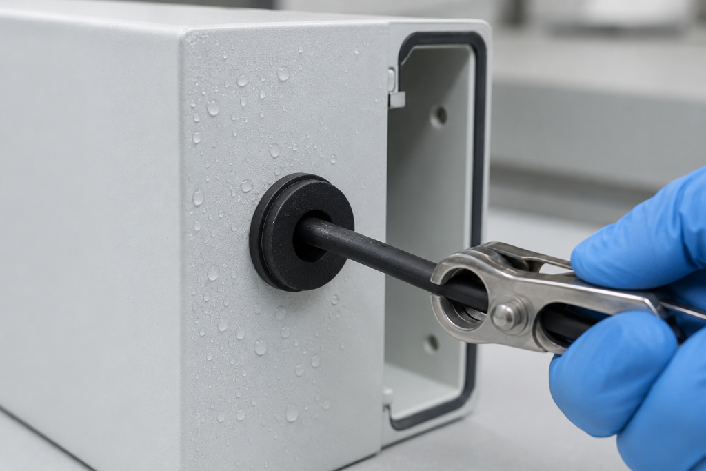
What Does a Cable Grommet Need to Do?
Before developing the geometry, define the required functions.
Edge Protection
The grommet isolates the cable jacket from a sharp panel edge. This is the most basic type of cable grommet and does not necessarily provide sealing or strain relief.
Cable Positioning
The grommet keeps the cable centered and limits movement against the panel.
Pull-Out Resistance
The grommet resists axial movement when the cable is pulled. This may be sufficient for light-duty positioning, but it should not automatically be treated as certified strain relief.
Bend Protection
An extended sleeve or tapered boot can reduce the bending stress where the cable exits the enclosure.
Environmental Sealing
A sealing grommet closes the leakage path between:
- The grommet and panel
- The grommet and cable
Both interfaces must remain sealed after installation, cable movement, aging and temperature exposure.
Grommet, Strain-Relief Bushing or Cable Gland?
These products may look similar but serve different purposes.
| ประเภทสินค้า | Edge protection | Cable retention | Environmental sealing |
|---|---|---|---|
| Open-hole grommet | ใช่ | Limited | Normally no |
| Sealing cable grommet | ใช่ | Design-dependent | Possible |
| Strain-relief bushing | ใช่ | Primary function | Design-dependent |
| Bend-protection boot | ใช่ | Limited unless separately anchored | Design-dependent |
| Cable gland | ใช่ | Designed for anchorage | Commonly available |
| Overmolded cable entry | ใช่ | Can be high | Can provide strong sealing |
IEC 62444 specifies construction and performance requirements for complete cable glands used in electrical installations. It does not automatically apply to a simple push-in silicone grommet. IEC 62444:2010
If the application requires certified cable anchorage, a compliant cable gland, separate cable clamp or overmolded strain-relief structure may be more appropriate than relying only on a soft grommet.
Silicone Cable Grommet Applications
Custom silicone grommets are used in:
- Outdoor electronic enclosures
- ตัวเรือนเซ็นเซอร์
- LED lighting
- ระบบแบตเตอรี่
- Chargers and power supplies
- Household appliances
- Medical equipment
- Automotive electronics
- Industrial control systems
- Marine equipment
- Communication devices
- Cable harness assemblies
Silicone is particularly useful where flexibility, temperature resistance or outdoor durability is important. The exact material grade must still be selected according to the application’s temperature, fluid exposure, UV, flammability and regulatory requirements.
Panel Cutout Design
The panel cutout is one of the most important dimensions in the complete assembly. A cutout that is too large can reduce retention and sealing pressure. A cutout that is too small can make installation difficult or damage the grommet.
Cutout Diameter
For a round grommet, the panel opening is normally specified by its finished diameter rather than the nominal size of the punching or drilling tool.
The drawing should define:
- Nominal cutout diameter
- Diameter tolerance
- Circularity
- Burr allowance
- Edge-break requirement
- Panel thickness
- Surface coating condition
- Inspection method
Do not specify the cutout before confirming the molded grommet dimensions and silicone hardness.
Panel Thickness
The grommet’s retaining groove must match the actual panel-thickness range.
If the panel is thinner than expected:
- The grommet may move axially.
- The sealing lip may not compress sufficiently.
- The grommet may rotate.
- Pull-out resistance may decrease.
If the panel is thicker than expected:
- Installation force may become excessive.
- The retaining lip may not fully engage.
- Silicone may tear during installation.
- The flange may distort.
- The seal may become uneven.
Commercial sealing grommets are normally specified by cable-diameter range, panel opening and allowable panel thickness. Trelleborg’s IP67 grommet data, for example, lists these dimensions separately and offers silicone options for selected sizes. Trelleborg IP67 cable grommets
Groove Width
The axial groove width should be designed for the panel thickness and the required compression.
A loose groove simplifies installation but may allow movement and leakage. A highly compressed groove can improve retention but may cause tearing or excessive assembly force.
The groove should be evaluated at:
- Minimum panel thickness
- Nominal panel thickness
- Maximum panel thickness
- Minimum molded groove width
- Maximum molded groove width
Retaining-Flange Diameter
The flange or locking lip must overlap the panel opening sufficiently to prevent the grommet from being pushed or pulled through the hole.
Increasing flange diameter can improve retention, but it also increases:
- Installation force
- Required space around the cutout
- Risk of flange folding
- Material usage
The inner and outer flanges may need different dimensions if cable loads are primarily applied in one direction.
Cutout Edge Condition
Sharp burrs can cut the silicone during installation or cable movement.
Specify an appropriate:
- Deburring process
- Edge break
- Corner radius
- Surface-finish limit
- Coating condition
Avoid an excessively large chamfer if the flange needs a defined flat surface for sealing.
Round, Oval and Non-Round Openings
Round cutouts are generally easier to manufacture, inspect and seal. Oval or rectangular openings may be needed for flat cables, connectors or anti-rotation.
Non-round designs require particular attention to:
- Corner radii
- Grommet orientation
- Local flange compression
- Panel-cutout tolerance
- Installation direction
- Mold parting-line location
Sharp internal corners should be avoided because they increase both panel stress and silicone-tearing risk.
Cable Diameter and Sealing Interference
A sealing grommet normally uses an opening smaller than the cable outside diameter. The stretched silicone creates radial pressure against the cable jacket.
The nominal cable interference can be expressed as:
Interference (%) = (Cable OD − Grommet bore ID) ÷ Cable OD × 100
There is no universal interference percentage suitable for every cable and grommet.
ค่าที่ถูกต้องขึ้นอยู่กับ:
- Cable diameter
- Cable-diameter tolerance
- Cable ovality
- Jacket material
- Jacket hardness
- Jacket surface texture
- ความแข็งของซิลิโคน
- Sealing-lip thickness
- ความยาวการสัมผัส
- Installation method
- Required pull-out force
- ช่วงอุณหภูมิ
การรบกวนไม่เพียงพอ
การแทรกแซงที่น้อยเกินไปอาจก่อให้เกิด:
- น้ำรั่ว
- Dust ingress
- Cable movement
- Low pull-out force
- Inconsistent sealing after vibration
การแทรกแซงที่มากเกินไป
การแทรกแซงมากเกินไปอาจก่อให้เกิด:
- Difficult cable insertion
- Rolled or inverted sealing lips
- Cable-jacket damage
- การฉีกขาดของซิลิโคน
- Excessive local stress
- Distorted panel sealing
- High assembly variation
The design must work with both the smallest and largest permitted cable diameters.
Cable Jacket Compatibility
The grommet contacts the cable jacket continuously, so material compatibility matters.
Common cable-jacket materials include:
- PVC
- TPE
- TPU
- ซิลิโคน
- Rubber
- Polyethylene
- Fluoropolymer
Review the potential for:
- Plasticizer migration
- Surface softening
- Swelling
- Loss of friction
- Staining
- Chemical attack
- Adhesion between similar elastomers
- Changes after heat aging
A cable that feels secure during initial assembly may have lower retention after exposure to heat, oil or moisture.
Designing the Cable Sealing Area
Single-Lip Seal
A single sealing lip is compact and easy to mold. It may be sufficient for controlled indoor applications, but it provides limited redundancy.
Multiple Sealing Ribs
Multiple ribs create several contact zones around the cable. This can improve sealing reliability when cable diameter or surface texture varies.
The ribs should not be so sharp that they cut into a soft cable jacket.
Long Cylindrical Contact
A longer contact bore can increase friction and sealing area. However, it also increases cable insertion force and may trap or fold the sealing surface during assembly.
Pierced Membrane
A thin membrane can keep the enclosure closed before the cable is installed. The cable or an installation tool pierces the membrane during assembly.
Important risks include:
- Irregular tearing
- Uncontrolled slit length
- Membrane fragments
- Damage from a connector
- Leakage around small cables
- Reduced pull-out repeatability
A molded pre-slit membrane offers more controlled opening behavior, but flash and slit dimensions must be carefully inspected.
Blind Sealing Plug
Some designs can function as a closed plug when no cable is installed and as a grommet after the membrane is opened.
Do not assume the same IP rating applies in both configurations without testing both conditions.
Panel-Side Sealing
Cable sealing alone is not enough. Water can also pass between the outside of the grommet and the panel cutout.
Panel-side sealing may be created by:
- Radial compression around the cutout
- Axial compression between flanges
- A molded sealing bead
- Multiple panel-contact ribs
- A tapered locking section
The sealing surface should contact a flat, clean area around the entire cutout.
Potential leak paths include:
- Panel burrs
- Weld distortion
- Paint buildup
- Scratches
- Parting-line flash
- Sink or deformation in a plastic housing
- Incomplete flange engagement
- Local contamination
Pull-Out Force
Pull-out force is the axial force required to move the cable through the grommet, remove the grommet from the panel or cause another defined failure.
These are different failure modes and should be recorded separately.
Cable Slips Through the Grommet
This indicates that friction and cable interference are insufficient for the applied load.
Grommet Pulls Out of the Panel
This indicates inadequate flange overlap, groove engagement or panel retention.
Silicone Tears
The grommet may have insufficient tear strength, excessive interference, sharp geometry or a stress concentration around the panel groove.
Cable Jacket Is Damaged
The grommet may use excessive compression or overly sharp internal ribs.
Factors Affecting Pull-Out Force
Pull-out performance depends on:
- Cable-to-grommet interference
- Length of cable contact
- Number and shape of internal ribs
- ความแข็งของซิลิโคน
- Coefficient of friction
- Cable surface finish
- Panel thickness
- Retaining-lip geometry
- Direction of loading
- Temperature
- Cable conditioning
- Presence of water, oil or dust
- Aging and compression set
A larger interference fit may increase pull-out force, but it can also increase assembly force and sealing-lip damage. Pull-out force and assembly force should be optimized together.
How to Specify a Pull-Out Test
A drawing statement such as “high pull-out force” is not measurable. A useful test specification should define:
- Cable type and manufacturer
- Cable nominal diameter and tolerance
- Panel material and thickness
- Panel cutout dimensions
- Grommet installation condition
- Pull direction
- Pulling speed
- Preload
- Maximum load
- Load duration
- Permitted cable displacement
- Permitted grommet movement
- Acceptable failure mode
- Test temperature
- Wet or dry condition
- Pre-aging requirement
Testing should include the cable and panel combinations expected to produce the lowest retention.
A practical validation matrix includes:
- Minimum cable OD with minimum panel thickness
- Minimum cable OD with maximum panel thickness
- Maximum cable OD with minimum panel thickness
- Maximum cable OD with maximum panel thickness
Pull-Out Resistance Is Not Always Strain Relief
A sealing grommet can produce measurable pull-out resistance but still be unsuitable as the only cable anchor.
Use a separate internal clamp, cable tie feature, overmolded anchor or cable gland when:
- The cable can be pulled by the user.
- The cable supplies mains power.
- Safety certification requires anchorage.
- The cable is heavy.
- Vibration or repeated bending is expected.
- Pulling force could reach solder joints or terminals.
- Failure would expose live electrical parts.
The grommet can then focus on edge protection and sealing while the internal structure carries the mechanical load.
Understanding IP Sealing
The IP Code classifies the protection provided by electrical enclosures against access, solid foreign objects and water ingress. IEC 60529 is the primary international standard for this classification. IEC 60529:1989+A1:1999+A2:2013
The first IP digit relates to protection against solid objects and dust. The second digit relates to protection against water.
A grommet alone does not establish an enclosure’s IP rating. The rating applies to the tested assembly, including:
- Enclosure
- Panel cutout
- Grommet
- Cable
- Cable position
- Installation process
- Other joints and openings
An “IP67 grommet” should therefore be interpreted as a component designed to support IP67 performance when installed according to specified conditions—not as a guarantee that every enclosure using it will pass.
IP54, IP67 and Other Requirements
Different enclosure applications require different levels of protection.
For example, Trelleborg separates cable-grommet products intended for IP54 and IP67 applications and specifies different cable, opening and plate-thickness ranges. Trelleborg IP54 grommets
When defining an IP requirement, clarify:
- Required IP code
- Indoor or outdoor use
- Installation orientation
- Water pressure or immersion condition
- Test duration
- Cable movement during service
- Whether the cable is installed or absent
- Whether the product must pass before and after aging
- Any additional pressure-washing requirements
A higher second digit should not be assumed to cover every lower-level water-jet condition unless the applicable product standard or test plan requires it.
Common IP Leakage Paths
| Leakage path | Possible cause |
| Between cable and bore | Insufficient interference, cable ovality or damaged lip |
| Between grommet and panel | Incorrect cutout, wrong panel thickness or incomplete engagement |
| Through a membrane slit | Excessive slit length, tearing or flash |
| Along a cable surface | Jacket grooves, printed markings or irregular texture |
| At the mold parting line | Flash or dimensional mismatch |
| Around a preassembled connector | Membrane damaged during installation |
| After cable movement | Loss of sealing pressure or lip inversion |
| After aging | Compression set, swelling, hardening or jacket migration |
IP Validation Plan
1. Dimensional Inspection
Measure:
- Finished cutout
- Panel thickness
- Cable diameter and ovality
- Grommet groove width
- Grommet bore diameter
- Flange dimensions
- Sealing-lip condition
2. Installation Evaluation
Record:
- Grommet installation force
- Cable insertion force
- Assembly time
- Lip folding
- Tearing
- Operator variation
- Need for lubricant or installation tools
Any assembly lubricant must be compatible with the materials and included in validation testing.
3. Initial IP Test
Test the complete enclosure using the specified cable and grommet configuration.
4. Mechanical Preconditioning
Depending on the application, complete:
- Pull-out loading
- Cable bending
- Torsion
- Vibration
- Mechanical shock
- Repeated cable movement
5. Environmental Conditioning
Possible exposures include:
- High-temperature aging
- Low-temperature exposure
- Temperature cycling
- UV exposure
- Ozone
- Humidity
- Oil or chemical contact
- Salt-containing environments
6. Repeat the IP Test
A design should maintain the required protection after relevant mechanical and environmental stresses—not only when the grommet is newly installed.
ความแข็งของวัสดุ
Silicone hardness affects sealing pressure, installation and retention.
Softer Silicone
Potential advantages:
- Easier installation
- Better conformance to cable irregularities
- Lower stress on thin panels
- Improved sealing at low compression
Possible disadvantages:
- Lower pull-out resistance
- Flange folding
- Easier extrusion
- Greater dimensional deformation
Harder Silicone
Potential advantages:
- Higher retention
- Improved shape stability
- More defined locking engagement
- Easier automated handling
Possible disadvantages:
- Higher installation force
- Reduced conformity
- Increased tearing risk during insertion
- Greater cable-jacket stress
Hardness should be selected together with the geometry. Changing hardness without adjusting the bore, lips and panel groove can significantly alter performance.
Grommet Geometry for Bend Protection
If the cable repeatedly flexes near the enclosure, add a flexible sleeve or boot.
A bend-protection section should use:
- Gradual thickness transitions
- Smooth external radii
- Adequate flexible length
- No sharp step at the panel
- Controlled cable clearance
- Strain relief located away from the electrical termination
A very short, stiff sleeve can simply move the stress concentration to the end of the grommet.
Designing for Preassembled Connectors
A cable with a connector may not pass through the grommet’s sealing hole.
Possible solutions include:
- Split grommet
- Slotted membrane
- Hinged or two-piece cable entry
- Stretchable push-through membrane
- Grommet installed before connector termination
- Overmolded cable-entry assembly
Split grommets simplify installation but introduce an additional sealing path. The split-line geometry, compression and orientation must be validated.
Tolerance Analysis
A successful design should consider the complete dimensional stack.
| พารามิเตอร์ | Minimum-condition risk | Maximum-condition risk |
| Cable OD | Leakage and low pull-out force | High insertion force and lip damage |
| Panel cutout | Difficult installation | Low retention and panel leakage |
| Panel thickness | Loose axial fit | Incomplete flange engagement |
| Grommet bore ID | High assembly force | Low sealing pressure |
| Groove width | Difficult installation | Grommet movement |
| Flange diameter | Limited retention | Excessive assembly force or space use |
Do not evaluate each dimension independently. The worst assembly condition is often created by several tolerances acting in the same direction.
Manufacturing Considerations
Custom silicone cable grommets can be manufactured by compression molding, transfer molding or liquid silicone rubber injection molding.
Tooling should control:
- Bore diameter
- Groove width
- Flange thickness
- รูปทรงของซี่ปิดผนึก
- Membrane thickness
- Parting-line position
- Gate location
- Flash at sealing surfaces
- Air entrapment
- Demolding strain
The parting line should be kept away from critical cable and panel sealing surfaces where practical.
A gate vestige located on a thin flange may cause distortion or tearing. A vestige inside the cable bore may create a leakage path or damage the cable jacket.
การควบคุมแฟลช
Small amounts of flash can prevent proper sealing or make cable installation inconsistent.
Critical inspection areas include:
- Cable bore
- Sealing ribs
- Membrane slit
- Panel groove
- Retaining lips
- Flange sealing face
Flash limits should be specified by functional zone. “No flash” without an inspection method or measurable limit can create disagreement between the supplier and buyer.
Common Grommet Failures
| Failure | Likely cause | Corrective direction |
| Grommet falls out | Cutout too large, flange too small or silicone too soft | Review panel and retaining geometry |
| Grommet tears during installation | Sharp panel edge, excessive interference or poor tear strength | Deburr panel and revise geometry or material |
| Cable pulls through | Low cable interference or short contact length | Increase controlled grip or add separate anchorage |
| Cable cannot be inserted | Bore too small, lip too sharp or jacket friction too high | Optimize bore, lip and installation method |
| Water leaks around cable | Low interference, cable ovality or folded lip | Review cable tolerance and seal geometry |
| Water leaks around panel | Wrong groove width, burr or uneven panel | Improve panel interface and dimensional control |
| Grommet rotates | Loose panel fit or cable torque | Add anti-rotation geometry |
| Cable jacket is damaged | Excessive compression or sharp ribs | Increase sealing radii and reduce local stress |
| Seal fails after aging | Compression set or material incompatibility | Test alternative material and geometry |
| IP result varies by operator | Inconsistent flange engagement or cable installation | Add assembly fixtures and visual checks |
Prototype and Pilot Production
A prototype tool or replaceable mold insert is valuable when the design contains:
- An unproven cable-interference fit
- A thin pierceable membrane
- High pull-out-force requirements
- A wide cable-diameter range
- A non-round panel cutout
- Tight packaging space
- A demanding IP rating
Prototype testing should use production-representative silicone, cables, panels and surface coatings.
After the geometry is confirmed, conduct a pilot run to evaluate:
- Cavity-to-cavity variation
- แฟลช
- Bore dimensions
- Installation force
- Pull-out force
- IP performance
- Visual defects
- Packaging deformation
RFQ Checklist
Provide the following information when requesting a custom silicone cable grommet quotation:
- 2D drawing and 3D model
- Cable type and jacket material
- Minimum, nominal and maximum cable OD
- Connector dimensions, if preassembled
- Panel material
- Panel thickness and tolerance
- Cutout dimensions and manufacturing process
- Required edge protection
- Target pull-out force
- Permitted cable displacement
- Required IP code
- Operating temperature
- UV and ozone exposure
- Oil or chemical exposure
- Required silicone hardness
- สี
- Flammability requirements
- Annual production quantity
- Assembly method
- Required validation tests
- Packaging and cleanliness requirements
If the cutout and grommet geometry have not yet been finalized, provide the enclosure and cable assembly. The supplier can then recommend a coordinated panel opening and grommet design.
คำถามที่พบบ่อย
How large should the panel cutout be?
The cutout must be designed together with the grommet groove, flange diameter, panel thickness and silicone hardness. There is no universal offset that applies to every grommet.
Should the grommet bore be smaller than the cable?
A sealing grommet normally uses controlled interference between the bore and cable. The amount must be validated using the complete cable-diameter tolerance and jacket material.
Can a silicone grommet provide strain relief?
It can provide pull-out resistance, but it should not automatically be treated as certified strain relief. Safety-critical applications may require a cable gland or separate internal cable anchor.
Does an IP67 grommet make the enclosure IP67?
No. The IP rating applies to the complete tested enclosure assembly. Panel dimensions, cable diameter, installation and all other enclosure openings affect the result.
Should pull-out testing be performed before or after IP testing?
Initial performance should be established first. The IP test should then be repeated after relevant pull-out, bending, vibration and environmental conditioning.
Can one grommet seal several cable diameters?
A flexible membrane or multiple sealing ribs can accommodate a limited range, but the smallest cable must still seal and resist movement while the largest cable must install without damaging the grommet.
Is silicone suitable for outdoor cable grommets?
Silicone can provide good flexibility and environmental resistance, but the specific grade must be confirmed for UV, ozone, temperature, water and chemical exposure.
Can a grommet be installed around a cable with a connector?
Yes, using a split, slotted, stretchable or two-piece design. These configurations require additional sealing validation because the installation opening creates another potential leak path.
สรุป
A reliable silicone cable grommet is a system formed by the cable, grommet, panel and installation process. Panel cutout dimensions determine retention, cable interference influences sealing and pull-out force, and the complete enclosure determines the final IP performance.
Early DFM, tolerance analysis and prototype testing can prevent loose installation, cable damage, leakage and failed certification. Send your cable dimensions, panel drawing, required pull-out force and target IP rating for a custom grommet design and manufacturing review.
 English
  Japanese
  Korean
  German
  French
  Italian
  Spanish
  Dutch
Dutch  Chinese
  Portuguese
  Polish
  Czech
Czech  Hungarian
  Swedish
  Finnish
  Vietnamese
  Thai
Thai  Turkish
  Arabic
  Russian