
Silicone duckbill valves are compact, one-piece elastomeric check valves that allow fluid or gas to flow in one direction while restricting reverse flow. They contain no metal spring, ball, hinge or separate moving mechanism, making them suitable for applications where small size, quiet operation, corrosion resistance and low opening pressure are important.
Common applications include:
- Medical fluid delivery systems
- Breast pumps
- Respiratory equipment
- Soap and lotion dispensers
- Coffee machines
- Water appliances
- Packaging closures
- Automotive fluid systems
- Fuel-tank ventilation
- Drainage devices
- Laboratory instruments
Despite their simple appearance, duckbill valves are highly sensitive to lip geometry, slit quality, silicone hardness, wall thickness and installation compression. A small dimensional change can significantly affect crack pressure, forward flow and reverse leakage.
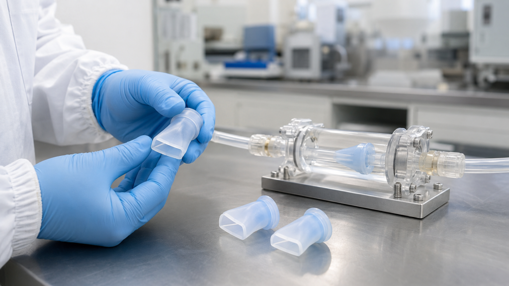
A reliable design must therefore balance three main performance targets:
- Low enough crack pressure to permit the required forward flow
- Low enough pressure drop at the target flow rate
- Sufficient backflow sealing under the specified reverse pressure
What Is a Silicone Duckbill Valve?
A duckbill valve normally consists of:
- An inlet barrel
- A mounting flange, sleeve or push-in feature
- A tapered flexible body
- Two flattened lips
- A precision slit between the lips
When pressure at the inlet exceeds pressure at the outlet, the lips deform and separate, creating a flow path. When pressure drops or reverses, the elasticity of the silicone and the reverse pressure force the lips together.
This provides passive one-way flow control without an external actuator.
Minivalve describes duckbill valves as one-piece elastomeric backflow-prevention devices whose lips open under forward flow and close when exposed to reverse pressure. Minivalve: How Duckbill Valves Work
Why Use LSR for Duckbill Valves?
Liquid silicone rubber is particularly suitable for small, flexible valve geometries because it offers:
- High molding precision
- Good flexibility across a broad temperature range
- Consistent elastic recovery
- Resistance to weathering and aging
- Availability in multiple hardness levels
- Low-viscosity filling of thin valve sections
- Clean molding for medical and food-contact applications
- Compatibility with automated, high-volume production
- Good colorability
- Potential for biocompatible and regulatory-compliant grades
LSR injection molding can produce thin, complex lip geometry with repeatable dimensions. However, the finished slit and valve performance still require careful process control.
Crack Pressure, Opening Pressure and Forward Flow
Crack pressure is commonly defined as the differential pressure at which measurable forward flow begins.
The pressure differential is:
ΔP = Inlet pressure − Outlet pressure
However, the term “crack pressure” can be misleading for duckbill valves.
Many duckbill valves are effectively normally open or begin deforming at a very low differential pressure. There may not be one sharp pressure point at which the valve changes instantly from fully closed to fully open.
Instead, the valve lips gradually separate as differential pressure increases. For this reason, crack pressure should always be connected to a defined flow threshold.
For example, a specification should not state only:
Crack pressure: 2 kPa
A more useful requirement would be:
Forward flow must reach at least 5 mL/min at a differential pressure of 2 kPa using water at 23°C.
Alternatively:
Opening pressure is the differential pressure measured when airflow first reaches 100 mL/min under the specified test conditions.
Vernay notes that the measured opening pressure depends on the flow threshold used to define valve opening. A higher measurement threshold can produce a higher reported opening-pressure value even when the valve itself has not changed. Vernay Duckbill Check Valve Design Guide
Important Valve Performance Terms
Several performance terms should be defined separately.
| Performance term | Meaning |
|---|---|
| Crack or opening pressure | Differential pressure at which a defined forward-flow threshold is reached |
| Forward pressure drop | Pressure difference across the valve at a specified flow rate |
| Maximum forward flow | Highest required flow under defined system conditions |
| Closing pressure | Pressure condition at which the lips return to their sealing position |
| Reverse leakage | Quantity of fluid or gas passing backward at a specified reverse pressure |
| Maximum reverse pressure | Highest backpressure the valve must withstand without inversion, damage or excessive leakage |
| Burst pressure | Pressure that causes structural rupture or permanent failure |
| Cycle life | Number of opening and closing cycles completed while meeting the performance limits |
These values must include test media, temperature, fixture condition and measurement method.
What Controls Duckbill Valve Crack Pressure?
Crack pressure is influenced by the combined stiffness and initial contact condition of the valve lips.
Silicone Hardness
A harder silicone compound generally requires more force to deform. Increasing hardness may raise crack pressure and reduce lip movement at a given pressure.
A softer compound may provide:
- Lower opening pressure
- Greater lip movement
- Higher flow at low pressure
- Better conformity between sealing surfaces
However, excessively soft silicone can cause:
- Dimensional instability
- Difficult demolding
- Lip distortion during assembly
- Valve inversion under backpressure
- Increased sensitivity to compression
- Slower elastic recovery
Hardness should not be selected alone. Modulus, elongation, tear strength and compression set also affect valve behavior.
ASTM D2240 is commonly used to measure rubber durometer hardness, but hardness remains an empirical control value rather than a complete description of valve stiffness. ASTM D2240
Lip Thickness
Lip thickness is one of the strongest design variables.
Thinner lips generally:
- Open more easily
- Reduce crack pressure
- Increase deformation at low forward pressure
Thicker lips generally:
- Require more pressure to open
- Provide greater resistance to inversion
- Improve dimensional stability
- Reduce maximum opening area at the same pressure
Very thin lips may tear during slitting or repeated cycling, especially if the slit ends contain notches.
Slit Length
A longer slit can create a larger flow opening and may reduce the differential pressure needed to achieve the required flow.
However, an excessively long slit can increase:
- Reverse leakage
- Lip instability
- Risk of tearing at the slit ends
- Sensitivity to particles
- Variation caused by blade positioning
The slit length must be balanced against lip thickness, valve width and expected backpressure.
Lip Contact and Preload
The two lips may be designed with light contact, controlled interference or a nearly neutral resting condition.
Greater lip contact can improve reverse sealing but may increase forward opening pressure.
Insufficient contact may reduce crack pressure but allow leakage before enough reverse pressure develops to force the lips together.
Duckbill Length
A longer tapered section is generally more flexible, while a short valve body is usually stiffer.
Increasing length can reduce the force required to deform the lips, but too much length can lead to:
- Buckling
- Sideways collapse
- Unstable flow
- Excessive movement inside the housing
Lip Angle and Taper
The transition from the round inlet to the flattened outlet controls how pressure is distributed through the valve.
A smooth taper can improve deformation and reduce local stress. Abrupt transitions may create high stress around the slit or produce unstable opening behavior.
Installation Compression
The housing can alter valve performance after assembly.
Radial or axial compression may:
- Increase crack pressure
- Force the lips together
- Distort the slit
- Restrict the inlet
- Improve or worsen reverse leakage
- Shift the valve away from its intended position
Performance testing should therefore be conducted in the production-intent housing rather than only on an uninstalled valve.
Design Variables and Their Typical Effects
| Design change | Typical crack-pressure effect | Typical flow effect | Possible risk |
| Softer silicone | Lower | Higher at low pressure | Distortion or inversion |
| Harder silicone | Higher | Lower at the same pressure | Poor low-pressure operation |
| Thinner lips | Lower | Higher | Tearing or inconsistent slitting |
| Thicker lips | Higher | Lower | Excessive pressure drop |
| Longer slit | Often lower | Higher | Increased leakage or tearing |
| Shorter slit | Often higher | Lower | Restricted flow |
| Greater lip preload | Higher | Lower initially | Difficult opening |
| Stronger housing compression | May increase | May decrease | Valve distortion |
| Larger inlet passage | Limited direct effect | Higher potential flow | Larger package size |
| Longer flexible bill | Often lower | May improve low-pressure flow | Buckling or unstable opening |
These are directional tendencies, not universal design rules. The interactions between geometry, material and housing must be verified through testing.
Designing for the Required Flow Rate
After the lips begin to open, forward flow depends on the effective opening area and pressure differential.
The flow curve usually shows:
- Differential pressure on one axis
- Flow rate on the other axis
At very low pressure, the slit may open only slightly. Flow then rises as the lips separate further. At higher pressure, the surrounding tube, housing or fluid channel may become the main flow restriction.
Factors That Affect the Flow Curve
Forward flow is influenced by:
- Slit length
- Lip thickness
- Duckbill width
- Inlet diameter
- Silicone modulus
- Available lip movement
- Housing clearance
- Upstream and downstream tubing
- Test-fluid viscosity
- Fluid density
- Gas compressibility
- Temperature
- Surface condition
- Particulate content
A valve tested with air cannot be assumed to produce the same flow behavior with water, oil, medication or a viscous cosmetic fluid.
Pressure Drop Must Include the Complete Assembly
Testing only the loose silicone component may provide misleading results.
The production assembly can introduce restrictions through:
- A small inlet port
- A retaining ring
- A narrow connector
- A sharp housing transition
- Incorrect valve compression
- Insufficient downstream clearance
The valve and housing should be evaluated as one fluid-control system.
Avoid Designing Only for Maximum Flow
A large slit and highly flexible lip may provide excellent forward flow but poor low-pressure sealing.
The target is not maximum possible flow. The target is adequate flow throughout the required operating-pressure window while still meeting reverse-leakage and durability requirements.
Backflow Prevention
When pressure reverses, the outlet pressure presses the two lips together. As reverse differential pressure increases, contact force between the lips normally increases.
This is the main sealing mechanism of a duckbill valve.
However, backflow performance is not absolute. Every practical valve specification should state a maximum allowable leakage rate under defined conditions.
For example:
- Less than 0.2 mL/min of air at 5 kPa reverse pressure
- No visible water leakage for 60 seconds at 20 kPa
- Pressure loss below a specified limit during a 30-second decay test
Minivalve notes that reverse leakage should be expressed as a measurable flow amount over time at a stated backpressure rather than simply described as “no leakage.” Minivalve: The Flow Curve
Low Reverse Pressure
Some duckbill valves require a small amount of reverse pressure before the lips are forced into full contact.
If the application requires sealing at an extremely low backpressure or at zero pressure differential, a duckbill valve may need:
- Greater lip preload
- A modified slit
- A different housing condition
- Surface treatment or lubrication
- A different elastomeric valve type
An umbrella valve, diaphragm valve or spring-assisted check valve may be more suitable for some zero-pressure sealing requirements.
Maximum Reverse Pressure
High backpressure can cause:
- Lip inversion
- Duckbill collapse
- Slit extension
- Permanent deformation
- Valve displacement from the housing
- Flange pull-through
- Material rupture
The valve, housing and retention method must all withstand the maximum reverse-pressure event, including pressure spikes.
Designing the Slit
The slit is the most critical functional feature of a silicone duckbill valve.
Slit Manufacturing Methods
Depending on valve design and production requirements, the slit may be produced by:
- Precision blade slitting
- Automated die cutting
- Punch slitting
- Laser cutting for selected applications
- A molded opening, where technically appropriate
Blade slitting is widely used because it can produce a fine, normally closed interface. However, performance depends on:
- Blade sharpness
- Blade thickness
- Cutting angle
- Slit depth
- Slit position
- Valve support during cutting
- Cutting speed
- Tool wear
- Silicone hardness
- Lubrication or surface condition
Slit-End Stress
The ends of the slit act as stress-concentration areas. Repeated opening can cause a small defect to grow into a tear.
High tear-strength LSR, suitable lip thickness and a controlled cutting process are therefore important.
ASTM D624 provides a method for evaluating rubber tear strength, although test-sheet results must still be supported by cycle testing on the actual valve. ASTM D624
Slit Cleanliness
A damaged or contaminated slit can cause reverse leakage.
Possible contaminants include:
- Silicone flash
- Cutting debris
- Dust
- Metal particles
- Fibers
- Mold-release residue
- Packaging particles
Medical and other clean-fluid applications may require controlled slitting, washing, inspection and clean packaging.
LSR Material Selection
The material should be selected according to the fluid, temperature, life cycle and regulatory requirements.
Hardness and Modulus
Lower hardness may support low-pressure opening, while higher hardness can improve stability. The final choice should be based on measured valve performance rather than hardness alone.
Tear Strength
High tear resistance is important because the lips repeatedly flex around a slit that already acts as an intentional discontinuity.
Compression Set
If the valve is compressed inside a housing for long periods, excessive compression set may change the lip position and cause performance drift.
Fluid Compatibility
The material must be tested with the actual media, including:
- Water
- Saline
- Medication
- Detergent
- Soap
- Cosmetic liquids
- Food and beverage ingredients
- Oil
- Fuel
- Cleaning chemicals
- Disinfectants
Standard VMQ silicone may perform well with water and many aqueous fluids but may not be suitable for prolonged fuel or hydrocarbon exposure. Fluorosilicone or another elastomer may be required for some applications.
Temperature Resistance
Temperature can change silicone stiffness and fluid viscosity. Both effects alter valve performance.
Testing may be needed at:
- Minimum operating temperature
- Room temperature
- Maximum continuous temperature
- Temporary temperature extremes
- Sterilization temperature
Regulatory Requirements
Depending on the application, material requirements may include:
- FDA food-contact compliance
- USP Class VI
- ISO 10993 biocompatibility evaluation
- RoHS
- REACH
- Phthalate restrictions
- Customer-specific extractables requirements
A regulatory material declaration does not automatically qualify the completed valve. The finished part, manufacturing process, additives, pigments and intended contact duration must also be considered.
LSR Injection Molding DFM
Duckbill valves often contain thin sections that require precise mold construction.
Gate Location
The gate should support balanced filling without creating excessive stress or weld lines near the slit area.
A gate placed too close to the lips may cause:
- Dimensional distortion
- Uneven lip thickness
- Difficult gate removal
- Cosmetic defects
- Localized stress
Venting
Air must escape from the thin lip region during filling. Poor venting can produce:
- Short shots
- Burned or damaged areas
- Trapped air
- Incomplete lips
- Surface defects
Because uncured LSR flows easily, vent dimensions must be small enough to limit flash.
Parting-Line Position
The parting line should not interfere with the lip-sealing surfaces or slit.
Flash near the slit can prevent complete closure and cause reverse leakage.
Mold Surface Finish
Surface finish can affect:
- Demolding
- Lip friction
- Slitting
- Fluid interaction
- Particle adhesion
The selected finish should be consistent across production cavities.
Demolding
The valve must be removed without stretching or damaging the lips.
Demolding design may require:
- Sufficient draft where appropriate
- Air-assisted release
- Carefully positioned ejector features
- Robotic handling
- Controlled mold coating
Installation and Housing Design
Duckbill valves are commonly installed using one of three configurations.
Flanged Valve
A flange is clamped between housing components.
Advantages include:
- Positive axial retention
- Simple assembly
- Integrated sealing potential
The clamping force must not excessively deform the inlet or lips.
Push-In Valve
A molded retention feature locks into a housing bore.
Important dimensions include:
- Bore diameter
- Interference
- Insertion force
- Pull-out force
- Retaining-bead geometry
Sleeved Valve
The valve fits over a rigid tube or nipple.
The interference must hold the valve securely without narrowing the flow path or distorting the duckbill.
Housing Clearance
The lips need sufficient space to open freely. Contact with the housing can restrict flow or produce asymmetric opening.
The downstream cavity should also avoid sharp features that may damage the lips during assembly or operation.
Performance Test Plan
A complete validation plan should evaluate both forward and reverse performance.
Crack-Pressure Test
The test setup should include:
- Controlled pressure source
- Pressure regulator
- Calibrated pressure sensor
- Flow meter
- Production-intent housing
- Defined test media
- Temperature control when required
Pressure should be increased at a controlled rate. The opening-pressure result should be recorded when the specified flow threshold is reached.
Forward Flow Test
Measure flow at several differential pressures across the operating range.
A useful flow curve includes:
- Low-pressure region
- Nominal operating point
- Maximum operating pressure
- Any plateau or instability
- Pressure after repeated cycling
Reverse Leakage Test
Apply reverse pressure and measure:
- Leakage volume
- Leakage rate
- Pressure decay
- Bubble formation
- Time to stabilize
The method must specify whether the media is air, water or the actual application fluid.
Maximum Reverse-Pressure Test
Increase backpressure to the required proof level and inspect for:
- Valve inversion
- Permanent deformation
- Flange movement
- Slit damage
- Leakage change
- Rupture
Cycle-Life Test
Repeatedly open and close the valve under representative pressure and flow conditions.
After cycling, recheck:
- Crack pressure
- Forward flow
- Reverse leakage
- Visual condition
- Slit length
- Permanent deformation
Environmental Conditioning
Performance may also be tested after:
- Heat aging
- Low-temperature exposure
- Thermal cycling
- Humidity aging
- Fluid immersion
- UV exposure
- Cleaning
- Sterilization
- Transportation vibration
- Storage aging
Common Duckbill Valve Problems
| Problem | Possible cause | Recommended action |
| Crack pressure is too high | Lips too thick, material too hard or excessive housing compression | Reduce stiffness or revise installation |
| Crack pressure is too low | Lips too flexible or slit too long | Increase lip control and evaluate reverse leakage |
| Forward flow is too low | Restricted slit, small inlet or insufficient housing clearance | Review complete flow path |
| Reverse leakage is excessive | Damaged slit, contamination or insufficient lip contact | Improve slit quality and sealing geometry |
| Valve leaks only after assembly | Housing distorts the valve | Revise bore, clamp or interference dimensions |
| Valve inverts under backpressure | Insufficient structural support or material stiffness | Strengthen body or reduce unsupported length |
| Slit tears during cycling | Poor cutting edge, low tear strength or high local strain | Improve slitting and lip design |
| Results vary between cavities | Tooling, wall thickness or slit-position variation | Audit cavity dimensions and cutting fixtures |
| Results drift with temperature | Material modulus or fluid viscosity changes | Test across the full temperature range |
| Valve sticks closed | Excessive lip contact or surface adhesion | Review surface treatment, geometry and storage |
| Particles become trapped in slit | Contaminated fluid or insufficient cleaning | Add filtration and controlled cleaning |
Prototype Development Strategy
A reliable custom valve is normally developed through several prototype iterations.
1. Define the System Requirements
Specify:
- Fluid or gas
- Fluid viscosity
- Operating temperature
- Minimum forward pressure
- Nominal and maximum flow
- Maximum pressure drop
- Reverse leakage limit
- Maximum backpressure
- Cycle-life target
- Sterilization or cleaning method
2. Select an Initial Valve Configuration
Choose:
- Flanged, push-in or sleeved installation
- Valve diameter
- Duckbill length
- Lip thickness
- Slit length
- Silicone hardness
- Housing compression
3. Produce a Prototype Matrix
Instead of testing only one geometry, compare controlled variations such as:
- Two lip thicknesses
- Two slit lengths
- Two hardness levels
- Different housing interference levels
4. Test in the Actual Housing
Loose-part tests are useful for screening, but final performance must be verified in the production-intent assembly.
5. Complete Pilot Production
Pilot production confirms:
- Molding consistency
- Slitting repeatability
- Assembly stability
- Cavity-to-cavity performance
- Test-fixture capability
- Packaging and cleanliness
Production Quality Control
Important production controls may include:
- LSR material lot
- Mixing ratio
- Mold temperature
- Cure time
- Critical lip dimensions
- Slit length and position
- Blade-life monitoring
- Flash inspection
- Visual contamination inspection
- Crack-pressure sampling
- Forward-flow sampling
- Reverse-leak testing
- Cycle testing by production lot
- Housing dimensional inspection
- Part and cavity traceability
For critical applications, performance data should be analyzed by cavity rather than combining all molded parts into one general sample group.
RFQ Checklist for Custom Silicone Duckbill Valves
To receive an accurate engineering review and quotation, provide:
- 2D drawing or 3D model
- Available installation space
- Preferred valve type
- Fluid or gas type
- Fluid viscosity
- Minimum and maximum temperature
- Minimum forward pressure
- Required flow rate
- Maximum permitted pressure drop
- Defined crack-pressure threshold
- Maximum reverse leakage
- Reverse-leak test pressure
- Maximum backpressure
- Required cycle life
- Silicone hardness preference
- Color requirement
- Regulatory requirements
- Sterilization method
- Housing material and dimensions
- Expected annual volume
- Prototype quantity
- Inspection-report requirements
- Packaging and cleanliness requirements
Avoid specifying only “low opening pressure” or “no leakage.” Both requirements must be converted into measurable acceptance criteria.
Frequently Asked Questions
What is the typical crack pressure of a silicone duckbill valve?
There is no universal value. Some duckbill valves begin flowing at very low differential pressure, while others are designed for a higher threshold. Geometry, hardness, slit design, housing compression, test media and flow threshold all affect the result.
Are duckbill valves normally open or normally closed?
Many duckbill valves are described as normally open because they begin forward flow at a very low pressure. However, the lips may still touch at rest. The terminology should not replace an actual flow and leakage specification.
Does a longer slit always increase flow?
A longer slit usually provides more potential opening area, but it can also increase leakage and slit-end stress. Flow may still be limited by the inlet, housing or tubing.
Can a duckbill valve prevent all reverse leakage?
No practical seal should be specified as absolutely leak-free without defining a test resolution. Reverse leakage should be stated as a maximum flow or pressure loss at a specified backpressure and test time.
Why does the valve leak after installation but not before installation?
The housing may be compressing, twisting or misaligning the valve. Installation dimensions should be included in performance validation.
Which silicone hardness is best?
The correct hardness depends on the required opening pressure, flow, backpressure and valve geometry. A softer material is not automatically better for every low-pressure application.
Can a silicone duckbill valve be used with oil or fuel?
Standard silicone may not provide adequate resistance to some hydrocarbon fluids. Fluorosilicone or another elastomer may be required. Compatibility testing with the actual media is essential.
How is the slit produced?
The slit is commonly created as a controlled secondary operation using a precision blade or cutting fixture. Slit position, length, blade condition and particle control directly affect performance.
Can duckbill valves handle particles?
The direct flow path can accommodate some suspended particles better than certain rigid check-valve designs. However, a particle trapped between the lips can still cause reverse leakage.
Is post-curing required?
It depends on the LSR grade, regulatory requirements, volatile limits and application. Material-supplier recommendations and final-part validation should determine the post-curing process.
Conclusion
A successful silicone duckbill valve is not designed around crack pressure alone. Opening pressure, forward flow and reverse leakage are interconnected.
Reducing lip stiffness may improve low-pressure flow but weaken reverse sealing. Increasing lip contact may reduce leakage but raise opening pressure. Housing compression may improve retention while unintentionally restricting the valve.
The most reliable development process includes:
- Clear flow and leakage specifications
- Production-intent material selection
- Controlled lip and slit geometry
- Housing-level validation
- Forward and reverse pressure testing
- Environmental conditioning
- Cycle-life testing
- Pilot production before mass manufacturing
For a custom silicone duckbill valve project, provide the operating media, required flow curve, acceptable reverse leakage, maximum backpressure, installation geometry and annual demand. These details allow the manufacturer to recommend a suitable LSR grade, valve structure, slit specification and test plan.
 English
  Japanese
  Korean
  German
  French
  Italian
  Spanish
  Dutch
Dutch  Chinese
  Portuguese
  Polish
  Czech
Czech  Hungarian
  Swedish
  Finnish
  Vietnamese
  Thai
Thai  Turkish
  Arabic
  Russian