
Liquid silicone rubber overmolding can combine a rigid metal insert with a flexible, heat-resistant and electrically insulating silicone layer in one finished component. The process is widely used for automotive connectors, medical instruments, electronic housings, vibration-damping parts, valves, handles and industrial sealing assemblies.
However, successful LSR-to-metal overmolding depends on more than choosing a suitable silicone grade. The metal alloy, surface finish, cleaning method, primer application, insert geometry, mold design and curing conditions all influence the final bond.
A component may appear acceptable after molding but fail during pull testing, thermal cycling, fluid exposure or repeated use. For this reason, the bonding method and validation plan should be established before production tooling is finalized.
What Is LSR Overmolding on Metal Inserts?
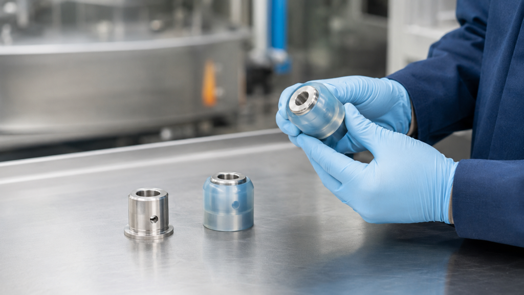
LSR overmolding is an insert-molding process in which a prefabricated metal component is placed inside a heated mold. Liquid silicone rubber is then injected around selected areas of the insert and cured inside the cavity.
The finished part combines two different material functions:
- The metal insert provides stiffness, electrical conductivity, threaded attachment, dimensional stability or structural support.
- The LSR layer provides sealing, insulation, cushioning, flexibility, grip, vibration control or environmental protection.
Common metal inserts include:
- Stainless steel tubes and housings
- Aluminum frames and brackets
- Carbon steel pins and plates
- Brass terminals
- Copper conductors
- Threaded bushings
- Electrical contacts
- Plated or coated metal stampings
The silicone can be chemically bonded to the metal, mechanically locked around the insert, or retained through a combination of both methods.
Why Overmold LSR Directly onto Metal?
Direct overmolding can replace several secondary assembly operations. Instead of molding the silicone part separately and then installing it with adhesive, clips or fasteners, the silicone and metal can become one integrated component.
Potential advantages include:
- Fewer assembly steps
- Reduced risk of incorrect seal installation
- Better protection against moisture and dust
- Improved resistance to vibration
- Consistent silicone positioning
- Lower part count
- Cleaner exterior geometry
- Easier automation at higher production volumes
- Reduced risk of silicone slipping or rotating on the insert
Overmolding is especially valuable when the silicone must remain permanently positioned on the metal during compression, pulling, twisting or thermal cycling.
Three Ways to Retain LSR on a Metal Insert
There are three main retention strategies.
1. Primer-Based Chemical Bonding
A compatible primer is applied to the metal before molding. During LSR curing, the primer promotes adhesion between the silicone and the metal surface.
Primer systems can provide strong bonding across many metals, but the process introduces additional control requirements:
- Surface cleaning
- Primer preparation
- Coating thickness
- Drying or baking time
- Storage time after priming
- Contamination prevention
- Operator and environmental controls
Dow, for example, offers primers specifically intended to bond LSR to aluminum, stainless steel and iron substrates. Primer selection must always be matched to the actual silicone grade, metal alloy and surface treatment. Dow SILASTIC DY 39-067 Primer
2. Self-Bonding or Primerless LSR
Self-bonding LSR contains adhesion-promoting chemistry designed to bond to selected metals or engineering plastics during molding.
This approach can eliminate a separate primer station and reduce labor, solvent handling and coating variation. However, “primerless” does not mean that the surface condition is unimportant.
The production insert must still be:
- Clean
- Dry
- Free from cutting oil
- Free from corrosion inhibitor
- Free from fingerprints
- Compatible with the LSR curing chemistry
Momentive describes self-bonding LSR grades that develop primerless adhesion to metals and engineering plastics. Its technical literature also notes that full bond strength may develop after post-curing or storage, depending on the specific grade. Momentive Silopren LSR 2750
3. Mechanical Locking
Mechanical locking uses the geometry of the metal insert to physically retain the cured silicone.
Typical features include:
- Through-holes
- Slots
- Circumferential grooves
- Undercuts
- Cross-holes
- Perforations
- Knurled areas
- Shoulders
- Flanges
- Windows through which the silicone can flow
Mechanical locking is useful when chemical adhesion is uncertain or when the application requires additional resistance to pull-out, twisting or peeling.
For critical components, a hybrid design combining chemical adhesion and mechanical locking usually provides the most robust solution.
Primer-Based, Primerless or Mechanical Retention?
| Bonding method | Main advantages | Main limitations | Suitable applications |
|---|---|---|---|
| Primer-based bonding | Broad substrate flexibility and potentially strong chemical adhesion | Additional coating, drying and handling operations | Industrial seals, metal housings, rollers and connectors |
| Self-bonding LSR | Fewer processing steps and easier automation | Must validate the exact metal, coating and LSR combination | High-volume insert-molded components |
| Mechanical locking | Less dependent on surface chemistry | Requires sufficient space and suitable insert geometry | Handles, grommets, reinforced seals and pull-resistant parts |
| Hybrid retention | Combines chemical and physical retention | More complex insert and tooling design | Safety-critical or high-load assemblies |
The best method depends on the product environment, required bond strength, production volume and available insert geometry.
Metal Selection and Surface Condition
The same LSR grade may bond differently to two inserts that appear visually identical. Small differences in alloy composition, plating, oxide condition, machining lubricant or surface treatment can significantly affect adhesion.
Aluminum
Aluminum is lightweight and easy to machine, but its natural oxide layer and surface treatments can vary.
Important variables include:
- Alloy and temper
- Machined, cast or stamped condition
- Natural, anodized or conversion-coated surface
- Cutting-fluid residue
- Oxide thickness
- Surface roughness
Anodizing may improve durability, but adhesion must be validated on the exact anodizing type, color, sealing condition and production supplier.
Stainless Steel
Stainless steel is common in medical, food-processing and industrial components. Its passive surface provides corrosion resistance but can also make adhesion sensitive to cleaning and activation methods.
The specification should identify:
- Stainless steel grade
- Surface finish
- Passivation process
- Polishing condition
- Cleaning method
- Any lubricant used during stamping or machining
Carbon Steel
Carbon steel can provide strong mechanical performance at a lower cost, but rust-preventive oil and corrosion must be controlled.
Paint, plating or conversion coatings may protect the insert, but the LSR bonds to the coating—not directly to the base steel. Coating adhesion therefore becomes part of the complete bond system.
Brass and Copper
Brass and copper inserts are frequently used in electrical components. Their surface oxidation, plating, stamping lubricants and storage conditions require careful control.
Compatibility testing is important because the actual insert may include nickel, tin, silver or another plated surface.
Plated Metal Inserts
When an insert is plated, the following questions should be answered:
- What is the plating material?
- What is the specified plating thickness?
- Is the overmolded area fully plated?
- Is a post-plating lubricant used?
- Can the plating supplier change without approval?
- Does the plating remain stable during LSR molding temperatures?
- Does the plating adhere strongly enough to the base metal?
A strong LSR-to-plating bond cannot compensate for poor adhesion between the plating and the underlying metal.
Surface Treatment Workflow for Reliable Bonding
Surface preparation is one of the most important parts of LSR-to-metal overmolding.
Step 1: Define the Production Surface
Prototype testing should use inserts that represent the final production alloy, finish, plating and cleaning process.
Testing a hand-polished laboratory sample is not sufficient if production parts will be stamped, passivated, anodized or coated by a different supplier.
Step 2: Remove Oil and Contamination
Metal surfaces must be free from:
- Machining oil
- Stamping lubricant
- Rust-preventive oil
- Polishing compound
- Dust
- Silicone contamination
- Fingerprints
- Adhesive residue
- Packaging residue
The cleaning process must be compatible with the metal, coating, primer and regulatory requirements of the finished product.
Step 3: Increase Surface Area When Necessary
Very smooth metal surfaces may benefit from controlled roughening.
Possible processes include:
- Abrasive blasting
- Glass-bead blasting
- Fine mechanical abrasion
- Laser texturing
- Chemical etching
Roughening can increase surface area and support mechanical interlocking, but excessive roughness may trap contamination, damage plating or create air pockets.
Wacker’s processing guidance states that surfaces to be primed should be dry and free from oil or grease and that very smooth surfaces may require roughening before primer application. Wacker Solid and Liquid Silicone Rubber Processing Guide
Step 4: Apply Surface Activation or Conversion Treatment
Depending on the metal and application, treatment may include:
- Plasma activation
- Corona treatment
- Chemical conversion coating
- Anodizing
- Passivation
- Laser cleaning
These treatments must be validated with the selected LSR and primer system. A treatment that improves corrosion resistance does not automatically improve silicone adhesion.
Step 5: Apply Primer Correctly
When primer is required, it should generally be applied as a thin, uniform film using a qualified process such as:
- Spraying
- Dipping
- Brushing
- Automated dispensing
Too little primer may produce incomplete coverage. Too much primer can cause pooling, inconsistent curing or weak internal primer layers.
Primer should be kept away from:
- Electrical contacts
- Threads that must remain clean
- Welding areas
- Cosmetic metal surfaces
- Mold shut-off surfaces
Step 6: Dry or Bake the Primer
Drying time, temperature and maximum storage time must follow the primer manufacturer’s technical data.
Some primers air-dry, while others may require heat activation or baking. Large overmolded areas may also require additional preparation to prevent the primer film from being damaged by silicone flow during injection.
Step 7: Protect the Treated Inserts
After treatment, inserts should be handled with clean gloves and stored in a controlled environment.
Important controls include:
- Maximum time between treatment and molding
- Temperature and humidity
- Dust protection
- Packaging material
- Tray cleanliness
- Lot identification
- First-in, first-out handling
Preventing LSR Cure Inhibition
Most technical LSR materials use platinum-catalyzed addition curing. Certain substances can interfere with the cure reaction at the metal-to-silicone interface.
Possible sources of cure inhibition include:
- Sulfur-containing materials
- Amines
- Some adhesives
- Certain rubber compounds
- Organotin-cured materials
- Contaminated release agents
- Processing oils
- Some paints and coatings
The result may be soft, sticky or uncured silicone at the interface even when the rest of the molded component appears fully cured.
Momentive recommends compatibility testing for all materials that contact self-bonding LSR, including painted surfaces, and specifically identifies several chemical families that may cause cure inhibition. Momentive Silopren LIM 9071 ET Technical Data
Metal Insert Design Rules
Good insert geometry can improve adhesion, molding stability and long-term reliability.
Add Mechanical Retention Features
Whenever space allows, include features through which the silicone can flow and cure.
Examples include:
- Holes through a metal flange
- Slots along the bonding area
- A circumferential groove around a pin
- A shoulder behind the silicone layer
- Knurled or textured retention zones
- Opposing undercuts
Mechanical retention is especially useful when the assembly will experience peeling, twisting or repeated vibration.
Avoid Sharp Metal Edges
Sharp edges can cut the silicone during demolding, assembly or use. They also concentrate stress at the edge of the bond.
Use suitable radii or chamfers where the silicone transitions from the metal surface.
Control Silicone Wall Thickness
Extremely thin silicone may tear, fail to fill or provide insufficient sealing movement. Excessively thick silicone may increase cure time, material cost and dimensional variation.
The wall thickness should be based on:
- Required flexibility
- Compression
- Tear risk
- Flow length
- Demolding method
- Bonding area
- Product tolerance
Gradual thickness transitions are generally more reliable than sudden changes.
Design for Balanced Flow
Gate position should allow the LSR to fill around the insert without trapping air or moving the insert.
Poor flow design can cause:
- Weld lines
- Air pockets
- Incomplete coverage
- Exposed metal
- Primer damage
- Insert movement
- Uneven bond strength
Vents should be placed near the final filling areas. Because LSR has very low viscosity, vent dimensions and shut-offs must be carefully controlled to prevent excessive flash.
Support the Insert in the Mold
The insert must remain stable during mold closing and injection.
Locating features may include:
- Pins
- Nests
- Magnetic loading fixtures
- Spring-loaded supports
- Vacuum-assisted holding
- Robotic loading fixtures
The insert should not rock, bend or float under injection pressure.
Protect Functional Metal Areas
Threads, electrical contacts, sealing faces and welding zones may need to remain free from silicone and primer.
These areas can be protected by:
- Precision mold shut-offs
- Removable masking
- Insert caps
- Dedicated locating surfaces
- Secondary cleaning, if permitted
Masking should not introduce contamination or leave residue on the bonding area.
Consider Thermal Expansion
Metal and silicone respond differently to temperature changes. Repeated heating and cooling can generate stress at the interface.
Long, continuous bond lines may benefit from:
- Flexible silicone transition zones
- Rounded bond edges
- Mechanical locking features
- Reduced peel loading
- Adequate silicone thickness
Tooling Considerations
Metal-insert overmolding requires more tooling controls than molding a silicone-only part.
Important tooling features include:
- Accurate insert location
- Repeatable shut-off pressure
- Flash control around the insert
- Venting at flow ends
- Easy insert loading
- Safe removal of the finished part
- Protection against insert scratching
- Sensor confirmation for automated loading
- Prevention of incorrect insert orientation
If the insert has dimensional variation, the tooling must accommodate the expected tolerance without losing shut-off control.
A small variation in insert thickness can create:
- Silicone flash
- Metal deformation
- Mold damage
- Incomplete closure
- Unstable silicone coverage
For this reason, insert tolerances should be reviewed together with mold tolerances during DFM.
LSR Processing Variables That Affect Adhesion
Even with the correct surface treatment and insert design, molding conditions can influence bond strength.
Mold Temperature
The insert and mold must reach a temperature that supports LSR curing and adhesion development. A cold or excessively massive insert may slow curing at the interface.
Cure Time
Insufficient cure time may produce acceptable-looking parts with weak or incomplete interfacial bonding.
Injection Speed and Pressure
High flow forces can move the insert, trap air or damage a primer layer. Very low speed may produce premature curing or incomplete filling.
Insert Preheating
Preheating may improve temperature uniformity and reduce cure variation, but the required temperature must be established through trials.
Post-Curing
Some LSR grades develop additional bond strength after thermal post-curing or room-temperature storage. Post-curing may also be required for selected regulatory or performance requirements.
The post-curing decision should be based on:
- Material supplier recommendations
- Required bond strength
- Volatile limits
- Regulatory requirements
- Final application temperature
- Production cost
How Is LSR-to-Metal Bond Strength Tested?
Visual inspection alone cannot confirm bond reliability.
90-Degree Peel Testing
A flexible silicone strip is peeled from a rigid substrate at a controlled angle and speed. The force is normally reported relative to the width of the bonded strip.
ISO 813:2019 specifies a 90-degree peel method for evaluating rubber bonded to a rigid substrate. ISO 813:2019
Comparative Peel Testing
ASTM D903 provides a method for comparing peel or stripping strength under defined specimen preparation and testing conditions. ASTM D903
Pull-Off or Tensile Testing
The silicone is pulled away from the insert perpendicular to the bonding surface. This can be useful for buttons, plugs, studs and circular inserts.
Pull-Out Testing
The metal insert is pulled from the molded silicone body. This method evaluates the combined effect of chemical adhesion and mechanical locking.
Torque Testing
The metal insert is rotated relative to the silicone. This is useful for knobs, shafts, handles and threaded components.
Functional Part Testing
A custom fixture applies the load expected in the final product, such as:
- Repeated bending
- Seal compression
- Cable pulling
- Connector insertion
- Valve cycling
- Vibration
- Pressure testing
Whenever possible, standard test plaques should be supplemented with tests on the actual molded component.
Bond Failure Modes
Bond strength values should be evaluated together with the observed failure mode.
Adhesive Failure
The silicone separates cleanly from the metal surface.
Possible causes include:
- Surface contamination
- Incorrect primer
- Insufficient primer coverage
- Incompatible metal coating
- Poor cure at the interface
- Insufficient surface activation
Cohesive Failure
The silicone tears while a layer remains bonded to the metal.
Cohesive failure usually indicates that the interface is stronger than the silicone material in the tested area.
Mixed Failure
Part of the silicone tears, while another portion separates from the metal.
Mixed failure may indicate inconsistent surface treatment, uneven primer coverage or variable molding conditions.
Environmental Validation
Initial bond strength is only one part of qualification. The assembly should also be tested after exposure to its expected operating environment.
Possible validation conditions include:
- High-temperature aging
- Low-temperature exposure
- Thermal cycling
- Temperature and humidity aging
- Water immersion
- Oil or fuel exposure
- Cleaning chemicals
- Salt spray
- UV exposure
- Steam sterilization
- Gamma sterilization
- Ethylene oxide sterilization
- Repeated mechanical cycling
The correct tests depend on the application. Automotive, medical, food-contact and electronic products may require different material grades and qualification protocols.
Common Problems and Corrective Actions
| Problem | Possible cause | Corrective action |
| Silicone peels cleanly from metal | Oil, fingerprints, incorrect primer or incompatible finish | Improve cleaning and validate the complete material system |
| Silicone remains sticky near the insert | Cure inhibition from coating, lubricant or contamination | Conduct compatibility testing and remove the contamination source |
| Bond strength varies between lots | Metal finish or primer process variation | Lock the insert specification and improve traceability |
| Strong initial bond but weak after aging | Corrosion, fluid penetration or thermal stress | Review surface protection, bond edge and environmental resistance |
| Silicone tears at the metal edge | Sharp edge or high peel stress | Add radii and reduce stress concentration |
| Insert moves during molding | Inadequate fixture support | Improve mold location and insert retention |
| Flash forms around the insert | Insert tolerance or shut-off variation | Tighten insert tolerances and redesign the shut-off |
| Silicone sticks to unwanted mold areas | Self-bonding material or release-control problem | Review mold coating and release strategy |
| Primer contaminates electrical contacts | Poor masking or uncontrolled spraying | Add targeted coating and protected handling fixtures |
Quality Control for Production
A stable production process should control both the incoming metal inserts and the overmolding operation.
Recommended controls include:
- Approved metal alloy and supplier
- Surface-finish specification
- Plating or treatment certificate
- Incoming visual inspection
- Cleanliness verification
- Primer lot and expiration tracking
- Primer mixing and application records
- Drying or baking time
- Maximum treated-insert storage time
- LSR batch traceability
- Mold temperature monitoring
- Cure-time records
- Insert-presence detection
- Dimensional inspection
- Periodic bond-strength testing
- Failure-mode recording
- Environmental validation by production lot when required
A water-break test, surface-energy check or visual primer inspection may help monitor the process, but these methods should not replace actual bond testing.
Prototype and Pilot Production Plan
A practical development program normally includes four stages.
Stage 1: Material Screening
Test combinations of:
- Metal alloys
- Surface finishes
- Cleaning methods
- Primer systems
- Self-bonding LSR grades
- Mechanical retention designs
Stage 2: Prototype Insert Molding
Produce representative parts using production-intent inserts and evaluate:
- Filling
- Insert movement
- Flash
- Silicone coverage
- Demolding
- Initial adhesion
Stage 3: Bond and Environmental Testing
Measure bond strength before and after relevant aging conditions. Record both force and failure mode.
Stage 4: Pilot Production
Run a controlled pilot batch to confirm:
- Insert-loading repeatability
- Cycle time
- Primer-process capability
- Dimensional stability
- Bond consistency
- Inspection method
- Packaging and storage
Pilot production is particularly important when inserts are supplied by an external metal stamping, machining, anodizing or plating company.
Cost Drivers
The cost of an LSR-overmolded metal component depends on more than silicone weight.
Major cost factors include:
- Insert material and machining
- Plating or surface treatment
- Cleaning requirements
- Primer application
- Insert-loading method
- Cavity quantity
- Mold shut-off complexity
- Silicone grade
- Cycle time
- Post-curing
- Bond testing
- Environmental validation
- Production volume
- Traceability requirements
- Packaging and contamination control
Self-bonding LSR may reduce primer-related labor, but the material cost and qualification requirements should be compared with the complete production process—not evaluated in isolation.
RFQ Checklist for LSR Overmolding on Metal
To receive an accurate quotation, provide:
- 3D CAD file
- 2D drawing
- Metal alloy and temper
- Insert manufacturing process
- Surface roughness
- Plating, anodizing or passivation details
- Areas that require silicone bonding
- Areas that must remain free of silicone
- Required silicone hardness
- Silicone color
- Regulatory requirements
- Operating temperature
- Chemical and fluid exposure
- Required bond-strength method
- Minimum pull, peel or torque requirement
- Preferred failure mode
- Dimensional tolerances
- Cosmetic requirements
- Expected annual volume
- Pilot-order quantity
- Required inspection report
- Packaging and cleanliness requirements
If the metal supplier or surface-treatment process may change, this should be discussed before validation. A supplier change can alter adhesion even when the drawing dimensions remain unchanged.
Frequently Asked Questions
Does LSR always require primer to bond to metal?
No. Some self-bonding LSR grades can bond directly to compatible metals. However, the exact metal alloy, surface finish, coating and molding conditions must be validated.
Can LSR bond to stainless steel?
Yes. LSR can be bonded to stainless steel using a compatible primer or a qualified self-bonding material. Cleaning, passivation and surface finish can influence the result.
Can LSR bond to anodized aluminum?
It may bond successfully, but the anodizing type, color, sealing process and surface condition must be tested. Different anodizing suppliers can produce different adhesion results.
Is sandblasting enough to create a reliable bond?
Not necessarily. Sandblasting increases roughness but does not remove every contaminant or provide chemical adhesion. Cleaning, primer selection and process validation may still be required.
What is considered good bond strength?
There is no universal value. The required force depends on the bonding area, silicone hardness, loading direction, product geometry and service environment. The customer should define a functional requirement and test method.
Is cohesive failure better than adhesive failure?
Cohesive failure generally indicates that the metal-to-silicone interface is stronger than the silicone in the tested region. However, the total measured force must still meet the application requirement.
Should mechanical locking be used if chemical bonding is available?
Mechanical locking is recommended when the geometry permits, especially for parts exposed to pulling, twisting, vibration or safety-critical loads. It provides additional protection against surface-process variation.
Can plated inserts be overmolded?
Yes, but the complete system must be tested. The LSR bonds to the plating surface, so plating adhesion, thickness, porosity and post-plating contamination must be controlled.
Does bond strength increase after molding?
Some self-bonding LSR grades continue building adhesion during room-temperature storage or thermal post-curing. Testing time should therefore be defined in the inspection standard.
How can silicone be kept away from threads or electrical contacts?
Precision mold shut-offs, masking fixtures, protective caps and controlled primer application can be used. These features should be considered during insert and mold design.
Conclusion
Reliable LSR overmolding on metal inserts requires coordinated control of material chemistry, metal preparation, insert geometry, tooling and process conditions.
The strongest design does not rely on only one factor. A robust component normally combines:
- A controlled metal surface
- A compatible primer or self-bonding LSR
- Mechanical retention where possible
- Rounded, low-stress bond edges
- Stable insert location
- Defined molding conditions
- Bond-strength and environmental testing
Early DFM and material testing can prevent weak adhesion, cure inhibition, flash, insert movement and expensive tooling modifications.
For a custom LSR-overmolded metal component, provide the insert drawing, metal specification, operating environment and required bond test. These details allow the manufacturer to recommend a suitable LSR grade, surface-treatment method, insert design and validation plan.
 English
  Japanese
  Korean
  German
  French
  Italian
  Spanish
  Dutch
Dutch  Chinese
  Portuguese
  Polish
  Czech
Czech  Hungarian
  Swedish
  Finnish
  Vietnamese
  Thai
Thai  Turkish
  Arabic
  Russian