
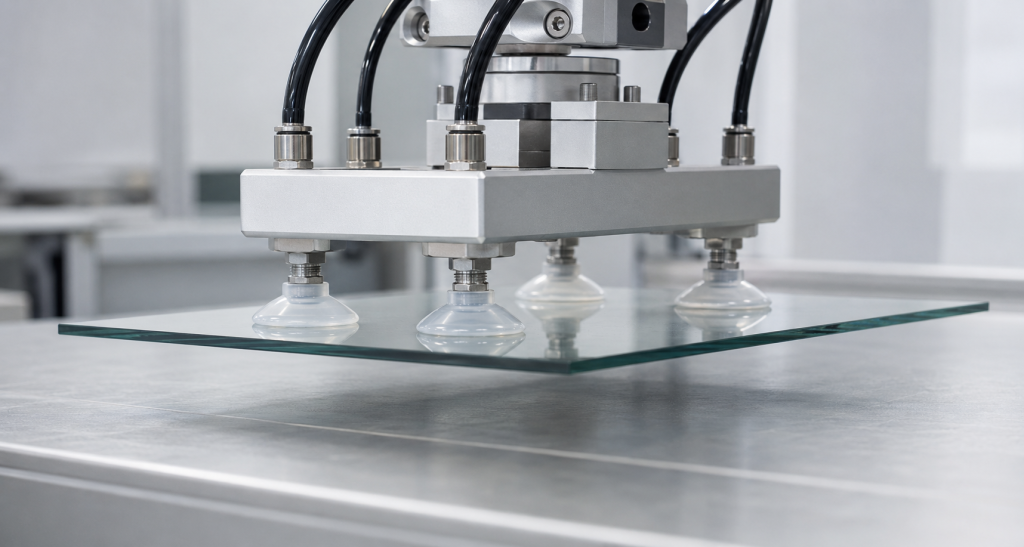
Silicone suction cups are used to lift, position, hold or temporarily attach products using a pressure difference between the inside of the cup and the surrounding atmosphere.
Zastosowania obejmują:
- Robotic pick-and-place systems
- Food and packaging equipment
- Glass handling
- Electronic component assembly
- Medical equipment
- Plastic-part handling
- Sheet-metal transfer
- Appliance manufacturing
- Consumer suction mounts
- Custom vacuum fixtures
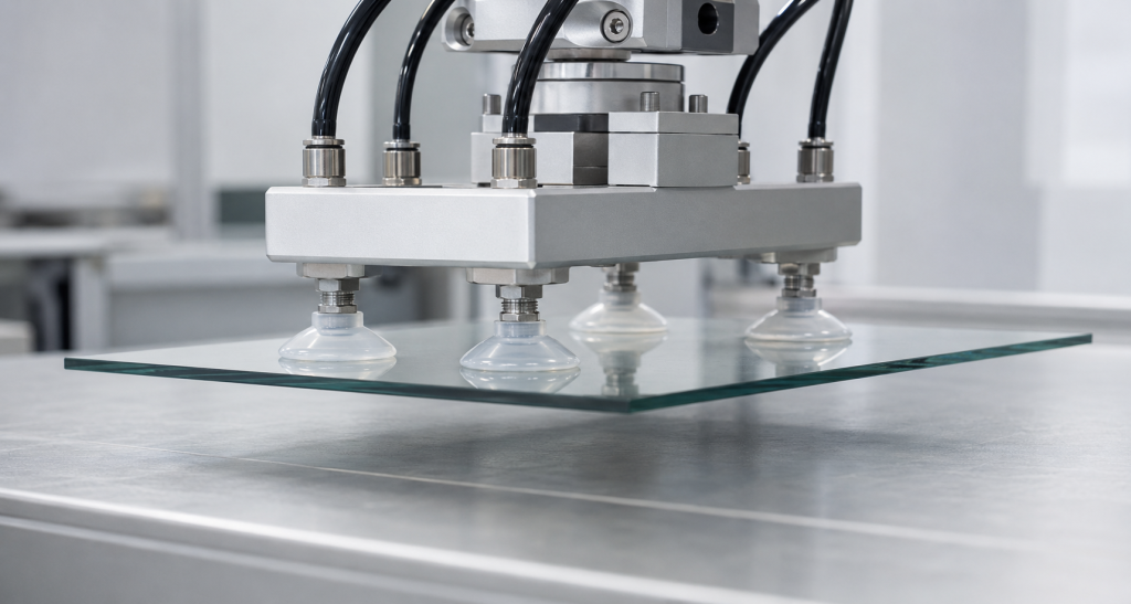
A suction cup that works on clean laboratory glass may fail on an oily metal panel, textured plastic housing or porous carton. Reliable performance depends on more than cup diameter or vacuum level.
Engineers must coordinate:
- Effective suction area
- Available vacuum pressure
- Safety factor
- Acceleration and load direction
- Workpiece surface
- Lip flexibility
- Cup geometry
- Twardość silikonu
- Vacuum flow capacity
- Leakage rate
- Service temperature and environment
How a Vacuum Suction Cup Generates Holding Force
When the suction cup contacts a surface, air is removed from the enclosed space. Atmospheric pressure outside the cup then pushes the cup against the workpiece.
The theoretical holding force is:
F = Δp × A
Where:
- F is theoretical holding force
- Δp is the difference between ambient pressure and pressure inside the cup
- A is the effective suction area
Schmalz uses the same relationship and emphasizes that suction force is proportional to pressure difference and effective area. Schmalz vacuum suction cup principles
Effective Area Is Not Always the Outside Diameter
The cup’s nominal outside diameter may be larger than its actual sealed area.
Effective area depends on:
- Inside diameter of the sealing lip
- Lip deformation
- Workpiece curvature
- Cup collapse
- Internal support ribs
- Vacuum level
- Surface irregularities
- Applied preload
Use the supplier’s published effective area when available. For a custom cup, determine effective area through geometry analysis and physical holding-force tests.
Example Holding-Force Calculation
Consider a cup with an effective diameter of 50 mm operating at a pressure difference of 60 kPa.
The effective area is approximately:
A = π × D² ÷ 4
A = 3.1416 × 0.05² ÷ 4 ≈ 0.00196 m²
The theoretical static holding force is:
F = 60,000 Pa × 0.00196 m² ≈ 118 N
This is roughly equivalent to the gravitational force on 12 kg, but it is not a safe working-load rating.
If a safety factor of 2 is applied before accounting for other losses, the preliminary working force is approximately:
118 N ÷ 2 = 59 N
Dynamic acceleration, side loading, surface leakage, load distribution and cup wear can reduce the permitted load further.
Why Theoretical Holding Force Is Not the Working Load
The theoretical formula assumes:
- A complete airtight seal
- Uniform pressure
- A stable effective area
- No acceleration
- No lateral load
- No surface contamination
- No hose or fitting leakage
- No cup deformation
- No wear
Real production systems rarely meet all these assumptions.
Schmalz states that calculated holding forces are theoretical and recommends verifying the actual application because cup geometry, surface finish and workpiece deformation affect performance. It also recommends using safety factors, with higher factors for swiveling loads. Schmalz suction cup design guidance
The final safety factor should follow the machine’s risk assessment, applicable regulations, load direction and consequences of a dropped part.
Load Direction
Normal Lifting
When the cup lifts a horizontal workpiece from above, the load acts approximately perpendicular to the sealing surface.
The suction force directly resists the load, although acceleration and moments must still be included.
Lateral or Shear Loading
When the cup holds a vertical panel, gravity acts parallel to the workpiece surface. The system then depends on friction between the cup and workpiece.
The available lateral force can be approximated as:
Fₗₐₜₑᵣₐₗ = μ × Fₙₒᵣₘₐₗ
Where:
- μ is the friction coefficient
- Fₙₒᵣₘₐₗ is the normal suction force
The friction coefficient must be measured using the actual silicone and workpiece condition.
Schmalz notes that no universally valid friction coefficient can be assigned because roughness, moisture, oil, cup material, lip geometry and hardness all influence the result. Schmalz holding-force calculation
Angled and Rotating Loads
Tilting or rotating a workpiece introduces both shear force and a peeling moment. The cup on one side of the load may carry substantially more force than the others.
Use higher safety margins and test the complete motion profile.
Dynamic Loads
For a moving system, the required force includes acceleration.
A simplified load estimate is:
Required force = Mass × (Gravity + Acceleration)
The analysis should include:
- Vertical acceleration
- Horizontal acceleration
- Robot emergency stop
- Direction reversal
- Rotation
- Workpiece vibration
- Collision or impact
- Hose forces
A system that safely holds a stationary part may release it during rapid acceleration.
Center of Gravity and Moments
The center of gravity should remain within the support area created by the suction cups.
If the load is offset:
- One cup may be overloaded.
- One lip may begin to peel.
- The workpiece may rotate.
- Vacuum may be lost at one edge.
Increase cup spacing, reposition the cups or use a stiffer support plate when the workpiece creates a large overturning moment.
Multiple Suction Cups
Using several cups can increase total capacity and stability, but the load may not divide equally.
Unequal loading can result from:
- Workpiece warpage
- Different cup heights
- Uneven mounting
- Hose pressure losses
- Surface variation
- Cup wear
- An offset center of gravity
Level compensators or bellows can help the cups contact the surface consistently.
The safety analysis should also consider what happens if one cup loses its seal.
Silicone Suction Cup Shapes
Flat Suction Cups
Flat cups provide good stability and limited inherent movement. They are suitable for relatively flat, smooth surfaces.
Piab describes its flat silicone cup design as suitable for flat objects, with internal cleats that help prevent thin products from deforming and improve friction under parallel loads. Piab flat silicone suction cups
Bellows Suction Cups
Bellows cups accommodate height differences, curved surfaces and some angular misalignment.
They can provide:
- Level compensation
- Softer contact
- Short lifting movement
- Improved adaptation to uneven workpieces
Do potencjalnych wad należą:
- Greater lateral movement
- Reduced positional accuracy
- Cup collapse at high vacuum
- More complex molding
- Increased fatigue at the folds
Deep Suction Cups
Deep cups can conform to curved or convex objects. The cup profile must match the expected workpiece curvature.
Oval Suction Cups
Oval cups fit long, narrow workpieces where a round cup of equivalent area would exceed the available width.
Zastosowania obejmują:
- Pipes
- Profiles
- Narrow packages
- Elongated electronic components
Oval cups require good anti-rotation support.
Multi-Lip Suction Cups
Multiple sealing lips provide additional contact lines and may improve sealing on slightly irregular surfaces. However, trapped contamination and higher molding complexity must be considered.
Sealing-Lip Design
The lip is the most critical part of the suction cup.
Important variables include:
- Lip thickness
- Lip angle
- Lip length
- Edge radius
- Root radius
- Inside diameter
- Outside diameter
- Wykończenie powierzchni
- Concentricity
- Twardość materiału
Thin Lips
A thin lip can conform to small surface irregularities and create a seal at low preload.
Potential risks include:
- Folding
- Wrinkling
- Rapid wear
- Tearing
- Sensitivity to flash
- Distortion during handling
Thick Lips
A thicker lip is more stable and wear-resistant but may require greater preload and may not conform to textured surfaces.
Lip Edge
The sealing edge should be smooth and continuous.
Avoid:
- Mold parting lines on the sealing edge
- Flash
- Gate vestiges
- Sharp notches
- Zanieczyszczenie powierzchni
- Local thickness changes
A small defect at one location can create a continuous leakage path.
Internal Cleats and Support Ribs
Internal cleats can:
- Prevent thin workpieces from being drawn deeply into the cup
- Maintain effective vacuum volume
- Increase friction
- Limit cup collapse
- Support films and sheets
The cleats should not mark the product or block airflow between different areas of the cup.
Vacuum Port Design
The vacuum port should evacuate the cup efficiently without pulling flexible material into the opening.
Zastanów się:
- Port diameter
- Port location
- Filter or mesh
- Internal flow channels
- Hose diameter
- Fitting restriction
- Risk of workpiece blockage
A port that is too small can increase evacuation time. A port that is too large may allow thin film to be drawn into the opening.
Flat, Smooth and Nonporous Surfaces
Examples include:
- Glass
- Polished metal
- Coated sheet
- Smooth plastic
- Glazed ceramic
These surfaces generally produce low leakage, but contamination can still reduce performance.
Inspect for:
- Oil
- Kurz
- Water films
- Protective coatings
- Zadrapania
- Tekstura pleśni
- Surface curvature
Rough or Textured Surfaces
Textured plastic, cast metal and patterned products contain microscopic paths under the sealing lip.
Possible design responses include:
- Softer silicone
- Thinner lip
- Wider sealing zone
- Multiple sealing lips
- Higher vacuum flow
- Larger cup
- Lower handling acceleration
Increasing vacuum depth alone may not overcome a continuous leakage path.
Porous Surfaces
Cardboard, wood, fabric and foam may allow air to pass through the workpiece itself.
For porous materials, the vacuum source must remove air continuously at a sufficient flow rate. A cup may reach only a moderate vacuum level but still hold the part if flow capacity is adequate.
High-flow or area-gripping systems may be more suitable than a conventional sealed cup.
Schmalz notes that leakage compensation through high airflow enables some vacuum systems to handle porous workpieces. Schmalz vacuum-generation principles
Oily or Wet Surfaces
Oil and water can affect:
- Friction
- Lip sealing
- Cup movement
- Zanieczyszczenie powierzchni
- Silicone compatibility
- Release behavior
A wet surface may seal effectively in the normal direction but provide very low lateral friction.
Test both holding force and slip resistance under the worst expected contamination level.
Curved Surfaces
The cup must contact the surface around its complete sealing perimeter.
For convex parts:
- The lip needs enough flexibility to wrap around the curvature.
- The cup body must not bottom out before the lip seals.
- The fitting should remain clear of the workpiece.
For concave parts:
- Cup edges may bridge across the surface.
- Effective area can change.
- Air can remain trapped in irregular regions.
Specify the minimum and maximum surface radius in the RFQ.
Flexible Films and Bags
Thin film can be drawn into the cup, block the vacuum port or become permanently creased.
Use:
- Internal support cleats
- Controlled vacuum level
- Larger contact area
- Thin conformable lips
- Adequate airflow
- Gentle release pressure
Piab offers reinforced multi-bellows silicone cups intended for bags containing liquids, viscous products and frozen food, demonstrating how cup geometry and reinforcement must be matched to the workpiece. Piab silicone multi-bellows cup
Hot and Cold Workpieces
Silicone can be suitable for a broad temperature range, but the complete cup assembly must be evaluated.
Temperature affects:
- Twardość silikonu
- Lip recovery
- Friction
- Vacuum hose
- Metal fitting
- Adhesive or insert bond
- Product surface
- Cycle life
Do not apply the silicone compound’s maximum temperature directly as the continuous working limit of the completed suction cup.
Food-Contact Applications
Some silicone formulations can meet food-contact requirements, but silicone is not automatically food-grade.
Potwierdź:
- Applicable food-contact regulation
- Pigment compliance
- Cure and post-cure process
- Metoda czyszczenia
- Extractables
- Traceability
- Maksymalna temperatura
- Contact time
Piab lists selected transparent silicone cups as compliant with FDA 21 CFR 177.2600 and EU 1935/2004. This is grade-specific and should not be generalized to every silicone material. Piab food-contact silicone suction cups
Twardość silikonu
Bardziej miękki silikon
Potential advantages:
- Better surface conformity
- Lower contact preload
- Improved sealing on minor texture
- Gentle handling of fragile products
Possible disadvantages:
- Greater cup deformation
- Lower lateral stability
- Lip folding
- Faster wear
- More difficult dimensional inspection
Twardszy silikon
Potential advantages:
- Better shape retention
- Greater lateral stability
- Improved handling during assembly
- Reduced collapse
Possible disadvantages:
- Higher preload
- Ograniczona zgodność
- Increased risk of leakage on rough surfaces
- Greater marking pressure
Hardness must be selected together with lip thickness and cup geometry.
Chemical Compatibility
Suction cups may contact:
- Oils
- Grease
- Środki czyszczące
- Food fats
- Detergents
- Coolants
- Release agents
- Solvents
ASTM D471 provides comparative methods for evaluating changes in rubber after liquid exposure, including changes in mass, volume, hardness and tensile properties. ASTM D471-16a(2021)
Test the production silicone and complete suction cup after exposure to the actual process fluid.
Understanding Vacuum Leakage
Leakage is the airflow entering the vacuum system while the cup is attached.
It can occur through:
- The cup-to-workpiece sealing edge
- A porous workpiece
- Surface scratches
- Tekstura pleśni
- Cup cracks
- Fittings
- Węże
- Zawory
- Insert-to-silicone interfaces
- Molded flash or defects
A stable vacuum requires the vacuum source to remove air at least as quickly as it enters.
Vacuum Depth Versus Vacuum Flow
Vacuum depth and airflow are different parameters.
- Vacuum depth determines the available pressure difference.
- Vacuum flow determines how quickly the system evacuates and compensates for leakage.
For a smooth, sealed surface, a relatively low-flow source may maintain vacuum once the cup is evacuated.
For a porous or leaking surface, high flow may be more important than achieving deep vacuum.
Vacuum-Decay Testing
Vacuum-decay testing evaluates the sealing quality of the cup and workpiece interface.
A typical method includes:
- Place the cup on the production-representative surface.
- Apply a defined preload.
- Evacuate to the target vacuum level.
- Isolate the vacuum source.
- Record pressure change over a defined time.
- Repeat at the expected temperature and surface conditions.
Specify:
- Initial vacuum
- Czas stabilizacji
- Czas trwania testu
- Maximum pressure rise
- Workpiece material
- Wykończenie powierzchni
- Cup conditioning
- Test temperature
- Applied preload
Leakage-Flow Testing
For continuously leaking surfaces, isolating the vacuum source may cause immediate release.
Instead, measure the airflow required to maintain a specified vacuum level.
This method is useful for:
- Porous cardboard
- Wood
- Textured plastic
- Fabric
- Foam
- Rough castings
The vacuum generator should provide sufficient flow with an appropriate safety margin.
Pull-Off Testing
A pull-off test measures the force required to separate the cup from the surface in the normal direction.
The test should define:
- Vacuum level
- Cup preload
- Czas przebywania
- Pulling speed
- Pull direction
- Workpiece surface
- Temperatura
- Cup age
- Liczba cykli
Peak pull-off force may include elastic adhesion and peeling effects. Do not use the maximum laboratory value directly as the machine’s safe working load.
Lateral Slip Testing
For vertical or angled surfaces, test the force required to initiate sliding.
Measure using:
- Actual silicone formulation
- Actual surface finish
- Dry condition
- Wet condition
- Oily condition
- Minimum and maximum temperature
The lowest repeatable value should be used in the design calculation with an appropriate safety factor.
Dynamic Holding Test
A production-representative test should reproduce:
- Robot acceleration
- Deceleration
- Rotation
- Direction changes
- Expected cycle time
- Workpiece variation
- Hose movement
- Emergency-stop condition
Monitor the minimum vacuum level during the motion rather than only at the pickup position.
Release Behavior
Reliable pickup is only half of the process. The cup must release the workpiece predictably.
Release problems can result from:
- Soft lip adhesion
- Residual vacuum
- Static electricity
- Oily surfaces
- Sticky products
- Slow valve response
- Insufficient blow-off flow
Controlled positive-pressure blow-off can shorten release time, but excessive pressure may damage the lip or eject lightweight parts unpredictably.
Fatigue and Wear
Suction cups repeatedly flex during contact, evacuation and release.
Common wear locations include:
- Sealing edge
- Lip root
- Bellows folds
- Insert interface
- Areas contacting sharp product edges
A cycle-life test should include:
- Normal operating vacuum
- Actual preload
- Workpiece texture
- Handling frequency
- Temperatura
- Cleaning process
- Release pressure
- Periodic leak and force measurements
Replacement intervals should be based on performance change rather than visible failure alone.
Fitting and Insert Design
Custom silicone cups may include:
- Metal threaded inserts
- Plastic snap-in fittings
- Hose barbs
- Filters
- Check valves
- Reinforcement rings
The insert must withstand:
- Axial pull
- Torque
- Vacuum cycling
- Temperature changes
- Czyszczenie
- Hose loads
Possible attachment methods include:
- Mechanical locking
- Formowanie z nakładką
- Adhesive bonding
- Retaining rings
Mechanical undercuts are generally more reliable than depending only on surface adhesion.
Manufacturing Considerations
Custom silicone suction cups may be produced by:
- Liquid silicone rubber injection molding
- Formowanie tłoczne
- Transfer molding
- Silicone-to-metal overmolding
Critical tooling features include:
- Sealing-lip thickness
- Lip concentricity
- Położenie linii podziału
- Port geometry
- Bellows wall thickness
- Insert location
- Gate position
- Wentylacja
Flash Control
Flash at the sealing edge can create leakage or inconsistent holding force.
Specify flash limits for:
- Outer lip
- Inner sealing edge
- Vacuum port
- Bellows folds
- Insert interface
The most critical sealing edge should not require uncontrolled manual trimming.
Dimensional Inspection
Possible inspection methods include:
- Optical measurement
- Vision inspection
- Non-contact profile measurement
- Controlled plug gauges
- Wall-thickness measurement
- Vacuum-decay testing
- Pull-off-force sampling
Soft silicone deforms during contact measurement, so inspection force and fixture design must be controlled.
Common Suction-Cup Failures
| Failure | Likely cause | Corrective direction |
|---|---|---|
| Cup will not seal | Surface texture, damaged lip or low preload | Use a more flexible lip and inspect the surface |
| Vacuum is reached slowly | Restricted port or excessive system volume | Review port, hose and generator flow |
| Vacuum cannot be maintained | Continuous leakage or porous workpiece | Increase flow or change gripping technology |
| Cup slides sideways | Low friction, oil or insufficient normal force | Test friction and revise cup layout |
| Workpiece drops during acceleration | Dynamic force exceeds working capacity | Increase effective area or reduce acceleration |
| Lip folds inward | Lip too soft, thin or overcompressed | Revise geometry and preload |
| Thin film blocks the port | Insufficient internal support | Add cleats or a filter screen |
| Workpiece is marked | Excessive preload, vacuum or local pressure | Use softer geometry and better support |
| Cup remains attached during release | Residual vacuum or material adhesion | Improve valve response and blow-off |
| Early lip cracking | Abrasive surface, sharp edge or fatigue | Improve material, geometry or replacement interval |
| Uneven multi-cup loading | Height variation or warped workpiece | Add level compensation and improve mounting |
| Insert pulls out | Weak bonding or insufficient mechanical lock | Add undercuts and validate pull/torque strength |
Prototype Validation Plan
1. Surface Review
Collect production samples representing:
- Smoothest surface
- Roughest surface
- Minimum and maximum curvature
- Dry condition
- Wet or oily condition
- Maximum porosity
- Temperature extremes
2. Geometry Prototypes
Compare:
- Cup diameter
- Flat versus bellows designs
- Lip thickness
- Twardość silikonu
- Internal cleats
- Port size
3. Static Testing
Measure:
- Vacuum level
- Evacuation time
- Leakage rate
- Normal pull-off force
- Lateral slip force
4. Dynamic Testing
Run the actual movement profile with the maximum workpiece mass and worst center-of-gravity position.
5. Environmental Testing
Evaluate relevant:
- Temperatura
- Chemicals
- Cleaning cycles
- UV exposure
- Food-contact cleaning
- Abrasive contamination
6. Cycle-Life Testing
Monitor holding force and leakage at defined intervals until the replacement criterion or failure limit is reached.
7. Pilot Production
Check variation by:
- Mold cavity
- Material lot
- Insert lot
- Workpiece surface
- Test fixture
Lista kontrolna zapytania ofertowego
Provide the following information when requesting a custom silicone suction cup quotation:
- 2D drawing and 3D model
- Workpiece material
- Surface finish and roughness
- Surface curvature
- Workpiece porosity
- Maximum weight
- Center-of-gravity location
- Load orientation
- Robot acceleration
- Number and spacing of cups
- Available vacuum level
- Vacuum-source flow
- Required evacuation time
- Maximum leakage rate
- Temperature range
- Oil, chemical or cleaning exposure
- Food-contact requirements
- Twardość silikonu
- Fitting type and thread
- Required cycle life
- Permitted surface marks
- Annual production volume
- Inspection and traceability requirements
If the suction-cup dimensions have not been finalized, provide samples of the workpiece and the complete handling motion. This allows prototype geometries to be tested under realistic conditions.
Najczęściej zadawane pytania
How is suction-cup holding force calculated?
Theoretical holding force equals the pressure difference multiplied by the effective suction area. A safety factor, acceleration, load direction, friction, leakage and cup deformation must then be considered.
Is the outside diameter the effective suction diameter?
Not always. The effective area is normally determined by the inside sealing boundary and can change when the lip deforms.
Why does the cup hold glass but not textured plastic?
Glass is usually smooth and nonporous. Textured plastic creates leakage paths under the sealing lip and may require a softer lip, higher flow or a different cup geometry.
Does a deeper vacuum always improve performance?
No. A continuous leak may prevent deep vacuum, and some flexible cups can collapse or deform at excessive vacuum levels. Flow capacity may be more important on porous surfaces.
Are silicone suction cups suitable for oily surfaces?
They may seal, but oil can greatly reduce lateral friction and may affect the silicone over time. Holding, slip and compatibility tests are required.
Can silicone suction cups contact food?
Only when the specific silicone formulation, pigment, manufacturing process and finished component meet the applicable food-contact requirements.
Why does a suction cup fail during robot movement?
Acceleration, rotation or an offset center of gravity may create forces and moments higher than the static holding calculation.
How should vacuum leakage be tested?
Use vacuum-decay testing for sealed surfaces and leakage-flow testing for porous or continuously leaking surfaces. Define the vacuum level, preload, surface and test duration.
Wnioski
Reliable silicone suction-cup design requires more than selecting a diameter and vacuum pressure. Effective area establishes the theoretical force, while surface condition, friction, acceleration, leakage and cup geometry determine the usable working load.
Prototype testing on actual workpieces is essential, especially for textured, porous, curved, oily or flexible products. Send your workpiece samples, surface information, load, motion profile and available vacuum data for a custom suction-cup DFM and performance evaluation.
 English
  Japanese
  Korean
  German
  French
  Italian
  Spanish
  Dutch
Dutch  Chinese
  Portuguese
  Polish
  Czech
Czech  Hungarian
  Swedish
  Finnish
  Vietnamese
  Thai
Thai  Turkish
  Arabic
  Russian