
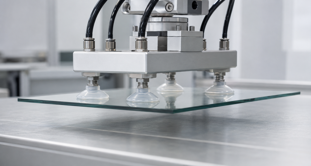
Silikonové přísavky se používají ke zvedání, polohování, přidržování nebo dočasnému upevňování výrobků s využitím rozdílu tlaku mezi vnitřkem přísavky a okolním prostředím.
Mezi oblasti použití patří:
- Robotické systémy pro manipulaci s díly
- Zařízení pro potravinářský průmysl a balení
- Manipulace se sklem
- Montáž elektronických součástek
- Zdravotnické vybavení
- Manipulace s plastovými díly
- Přenos plechů
- Výroba domácích spotřebičů
- Sací držáky pro spotřebitele
- Vakuová upínací zařízení na míru
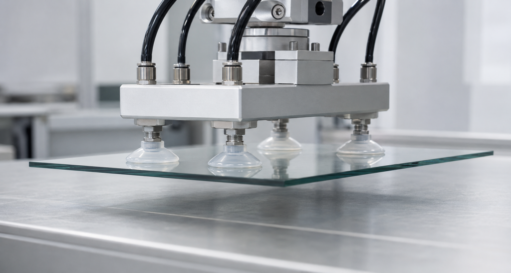
Přísavka, která funguje na čistém laboratorním skle, nemusí držet na mastném kovovém panelu, strukturovaném plastovém krytu nebo porézním kartonu. Spolehlivý výkon závisí na více faktorech než jen na průměru přísavky nebo úrovni podtlaku.
Inženýři musí koordinovat:
- Efektivní sací plocha
- Dostupný podtlak
- Bezpečnostní koeficient
- Zrychlení a směr zatížení
- Povrch obrobku
- Pružnost rtů
- Geometrie poháru
- Tvrdost silikonu
- Průtok ve vakuu
- Míra úniku
- Provozní teplota a okolní podmínky
Jak vakuová přísavka vytváří přilnavou sílu
Jakmile se přísavka dotkne povrchu, je z uzavřeného prostoru odsát vzduch. Atmosférický tlak vně přísavky pak přísavku přitlačí k obrobku.
Teoretická přídržná síla činí:
F = Δp × A
Kde:
- F je teoretická přídržná síla
- Δp je rozdíl mezi atmosférickým tlakem a tlakem uvnitř nádobky
- A je efektivní sací plocha
Společnost Schmalz vychází ze stejného vztahu a zdůrazňuje, že sací síla je úměrná rozdílu tlaků a účinné ploše. Principy fungování vakuových přísavek Schmalz
Účinná plocha se ne vždy rovná vnějšímu průměru
Jmenovitý vnější průměr kalíšku může být větší než jeho skutečná těsnicí plocha.
Účinná plocha závisí na:
- Vnitřní průměr těsnicího okraje
- Deformace rtů
- Zakřivení obrobku
- Krach v poháru
- Vnitřní výztužná žebra
- Úroveň podtlaku
- Nerovnosti povrchu
- Použité předpětí
Pokud je k dispozici, použijte efektivní plochu uvedenou dodavatelem. U šálku vyrobeného na zakázku určete efektivní plochu pomocí geometrické analýzy a fyzických zkoušek přídržné síly.
Příklad výpočtu přidržovací síly
Uvažujme nádobku s efektivním průměrem 50 mm, která pracuje při tlakovém rozdílu 60 kPa.
Efektivní plocha činí přibližně:
A = π × D² ÷ 4
A = 3,1416 × 0,05² ÷ 4 ≈ 0,00196 m²
Teoretická statická přídržná síla činí:
F = 60 000 Pa × 0,00196 m² ≈ 118 N
To zhruba odpovídá gravitační síle působící na 12 kg, nejedná se však o hodnotu bezpečného pracovního zatížení.
Pokud se před zohledněním dalších ztrát použije bezpečnostní koeficient 2, činí předběžná pracovní síla přibližně:
118 N ÷ 2 = 59 N
Dynamické zrychlení, boční zatížení, úniky na povrchu, rozložení zatížení a opotřebení misky mohou přípustné zatížení ještě dále snížit.
Proč teoretická přídržná síla není provozní zatížením
Teoretický vzorec vychází z následujících předpokladů:
- Úplně vzduchotěsné utěsnění
- Rovnoměrný tlak
- Stabilní účinná plocha
- Žádné zrychlení
- Žádné boční zatížení
- Žádné znečištění povrchu
- Žádné úniky z hadic ani armatur
- Žádné deformace kelímku
- Žádné opotřebení
Skutečné produkční systémy málokdy splňují všechny tyto předpoklady.
Společnost Schmalz uvádí, že vypočítané přídržné síly jsou teoretické, a doporučuje ověřit skutečné podmínky použití, protože výkon ovlivňuje geometrie přísavky, povrchová úprava a deformace obrobku. Dále doporučuje používat bezpečnostní koeficienty, přičemž u zatížení při otáčení je třeba použít vyšší koeficienty. Pokyny k návrhu přísavek Schmalz
Konečný bezpečnostní koeficient by měl vycházet z posouzení rizik stroje, platných předpisů, směru zatížení a následků případného pádu součásti.
Směr zatížení
Běžné zvedání
Když přísavka zvedá vodorovný obrobek shora, působí zatížení přibližně kolmo na těsnicí plochu.
Sací síla působí přímo proti zatížení, i když je třeba zohlednit také zrychlení a momenty.
Boční nebo smykové zatížení
Pokud je v upínacím kalíšku upevněn svislý panel, působí gravitace rovnoběžně s povrchem obrobku. Systém pak závisí na tření mezi upínacím kalíškem a obrobkem.
Dostupnou boční sílu lze přibližně vyjádřit jako:
Fₗₐₜₑᵣₐₗ = μ × Fₙₒᵣₘₐₗ
Kde:
- μ je koeficient tření
- Fₙₒᵣₘₐₗ je normální sací síla
Koeficient tření je třeba měřit za skutečných podmínek, v nichž se nachází silikon a obrobek.
Společnost Schmalz upozorňuje, že nelze stanovit žádný obecně platný koeficient tření, protože výsledek ovlivňují drsnost povrchu, vlhkost, olej, materiál misky, geometrie okraje a tvrdost. Výpočet přídržné síly u společnosti Schmalz
Šikmé a rotující zatížení
Naklopením nebo otočením obrobku vzniká jak smyková síla, tak odlupovací moment. Miska na jedné straně zatížení může nést podstatně větší sílu než ostatní.
Použijte větší bezpečnostní rezervy a otestujte celý pohybový profil.
Dynamická zatížení
U pohybujícího se systému zahrnuje potřebná síla i zrychlení.
Zjednodušený odhad zatížení je:
Potřebná síla = Hmotnost × (Gravitace + Zrychlení)
Analýza by měla zahrnovat:
- Vertikální zrychlení
- Vodorovné zrychlení
- Nouzové zastavení robota
- Změna směru
- Rotace
- Vibrace obrobku
- Srážka nebo náraz
- Síly působící na hadici
Systém, který bezpečně drží pevně uchycenou součást, ji může při prudkém zrychlení uvolnit.
Těžiště a momenty
Těžiště by mělo zůstat v oblasti opory vytvořené přísavkami.
Pokud je náklad posunut:
- Jeden šálek může být přeplněný.
- Jedna ret se může začít loupe.
- Obrobek se může otáčet.
- Na jednom okraji může dojít ke ztrátě podtlaku.
Pokud obrobek vyvolává velký převrácivý moment, zvětšete rozestup mezi upínacími čelistmi, změňte jejich polohu nebo použijte tužší opěrnou desku.
Více přísavek
Použití více šálků může zvýšit celkovou kapacitu a stabilitu, ale zátěž nemusí být rozložena rovnoměrně.
Nerovnoměrné zatížení může být způsobeno:
- Deformace obrobku
- Různé výšky šálků
- Nerovnoměrná montáž
- Tlakové ztráty v hadicích
- Odchylky povrchu
- Opotřebení kalíšku
- Posunuté těžiště
Vyrovnávací prvky nebo vlnovce mohou zajistit, aby se misky rovnoměrně dotýkaly povrchu.
Analýza bezpečnosti by měla rovněž zohlednit, co se stane, pokud jeden kelímek přestane těsnit.
Tvary silikonových přísavek
Ploché přísavky
Ploché misky zajišťují dobrou stabilitu a omezují vlastní pohyb. Jsou vhodné pro relativně rovné a hladké povrchy.
Společnost Piab popisuje svou konstrukci plochých silikonových přísav jako vhodnou pro ploché předměty; vnitřní výstupky zabraňují deformaci tenkých výrobků a zvyšují tření při paralelním zatížení. Ploché silikonové přísavky Piab
Přísavky s měchem
Měchové misky vyrovnávají výškové rozdíly, zakřivené povrchy a určité úhlové nesouososti.
Mohou poskytnout:
- Vyrovnání úrovně
- Jemnější kontakt
- Krátký zvedací pohyb
- Lepší přizpůsobení se nerovným obrobkům
Mezi možné nevýhody patří:
- Větší boční pohyb
- Snížená polohová přesnost
- Kolaps nádoby při vysokém vakuu
- Složitější lisování
- Zvýšená únava materiálu v ohybech
Hluboké přísavky
Hluboké kalíšky se dokážou přizpůsobit zakřiveným nebo konvexním předmětům. Profil kalíšku musí odpovídat předpokládanému zakřivení obrobku.
Oválné přísavky
Oválné upínací misky jsou vhodné pro dlouhé a úzké obrobky, u nichž by kulatá upínací miska se stejnou plochou přesahovala dostupnou šířku.
Mezi oblasti použití patří:
- Trubky
- Profily
- Úzké balíčky
- Elongated electronic components
Oval cups require good anti-rotation support.
Multi-Lip Suction Cups
Multiple sealing lips provide additional contact lines and may improve sealing on slightly irregular surfaces. However, trapped contamination and higher molding complexity must be considered.
Sealing-Lip Design
The lip is the most critical part of the suction cup.
Important variables include:
- Lip thickness
- Lip angle
- Lip length
- Edge radius
- Root radius
- Inside diameter
- Outside diameter
- Povrchová úprava
- Concentricity
- Tvrdost materiálu
Thin Lips
A thin lip can conform to small surface irregularities and create a seal at low preload.
Potential risks include:
- Folding
- Wrinkling
- Rapid wear
- Tearing
- Sensitivity to flash
- Distortion during handling
Thick Lips
A thicker lip is more stable and wear-resistant but may require greater preload and may not conform to textured surfaces.
Lip Edge
The sealing edge should be smooth and continuous.
Avoid:
- Mold parting lines on the sealing edge
- Flash
- Gate vestiges
- Sharp notches
- Kontaminace povrchu
- Local thickness changes
A small defect at one location can create a continuous leakage path.
Internal Cleats and Support Ribs
Internal cleats can:
- Prevent thin workpieces from being drawn deeply into the cup
- Maintain effective vacuum volume
- Increase friction
- Limit cup collapse
- Support films and sheets
The cleats should not mark the product or block airflow between different areas of the cup.
Vacuum Port Design
The vacuum port should evacuate the cup efficiently without pulling flexible material into the opening.
Consider:
- Port diameter
- Port location
- Filter or mesh
- Internal flow channels
- Hose diameter
- Fitting restriction
- Risk of workpiece blockage
A port that is too small can increase evacuation time. A port that is too large may allow thin film to be drawn into the opening.
Flat, Smooth and Nonporous Surfaces
Examples include:
- Glass
- Polished metal
- Coated sheet
- Smooth plastic
- Glazed ceramic
These surfaces generally produce low leakage, but contamination can still reduce performance.
Inspect for:
- Oil
- Dust
- Water films
- Protective coatings
- Scratches
- Mold texture
- Surface curvature
Rough or Textured Surfaces
Textured plastic, cast metal and patterned products contain microscopic paths under the sealing lip.
Possible design responses include:
- Softer silicone
- Thinner lip
- Wider sealing zone
- Multiple sealing lips
- Higher vacuum flow
- Larger cup
- Lower handling acceleration
Increasing vacuum depth alone may not overcome a continuous leakage path.
Porous Surfaces
Cardboard, wood, fabric and foam may allow air to pass through the workpiece itself.
For porous materials, the vacuum source must remove air continuously at a sufficient flow rate. A cup may reach only a moderate vacuum level but still hold the part if flow capacity is adequate.
High-flow or area-gripping systems may be more suitable than a conventional sealed cup.
Schmalz notes that leakage compensation through high airflow enables some vacuum systems to handle porous workpieces. Schmalz vacuum-generation principles
Oily or Wet Surfaces
Oil and water can affect:
- Friction
- Lip sealing
- Cup movement
- Kontaminace povrchu
- Silicone compatibility
- Release behavior
A wet surface may seal effectively in the normal direction but provide very low lateral friction.
Test both holding force and slip resistance under the worst expected contamination level.
Curved Surfaces
The cup must contact the surface around its complete sealing perimeter.
For convex parts:
- The lip needs enough flexibility to wrap around the curvature.
- The cup body must not bottom out before the lip seals.
- The fitting should remain clear of the workpiece.
For concave parts:
- Cup edges may bridge across the surface.
- Effective area can change.
- Air can remain trapped in irregular regions.
Specify the minimum and maximum surface radius in the RFQ.
Flexible Films and Bags
Thin film can be drawn into the cup, block the vacuum port or become permanently creased.
Use:
- Internal support cleats
- Controlled vacuum level
- Larger contact area
- Thin conformable lips
- Adequate airflow
- Gentle release pressure
Piab offers reinforced multi-bellows silicone cups intended for bags containing liquids, viscous products and frozen food, demonstrating how cup geometry and reinforcement must be matched to the workpiece. Piab silicone multi-bellows cup
Hot and Cold Workpieces
Silicone can be suitable for a broad temperature range, but the complete cup assembly must be evaluated.
Temperature affects:
- Tvrdost silikonu
- Lip recovery
- Friction
- Vacuum hose
- Metal fitting
- Adhesive or insert bond
- Product surface
- Cycle life
Do not apply the silicone compound’s maximum temperature directly as the continuous working limit of the completed suction cup.
Food-Contact Applications
Some silicone formulations can meet food-contact requirements, but silicone is not automatically food-grade.
Confirm:
- Applicable food-contact regulation
- Pigment compliance
- Cure and post-cure process
- Cleaning method
- Extractables
- Traceability
- Maximum temperature
- Contact time
Piab lists selected transparent silicone cups as compliant with FDA 21 CFR 177.2600 and EU 1935/2004. This is grade-specific and should not be generalized to every silicone material. Piab food-contact silicone suction cups
Tvrdost silikonu
Softer Silicone
Potential advantages:
- Better surface conformity
- Lower contact preload
- Improved sealing on minor texture
- Gentle handling of fragile products
Possible disadvantages:
- Greater cup deformation
- Lower lateral stability
- Lip folding
- Faster wear
- More difficult dimensional inspection
Harder Silicone
Potential advantages:
- Better shape retention
- Greater lateral stability
- Improved handling during assembly
- Reduced collapse
Possible disadvantages:
- Higher preload
- Reduced conformity
- Increased risk of leakage on rough surfaces
- Greater marking pressure
Hardness must be selected together with lip thickness and cup geometry.
Chemical Compatibility
Suction cups may contact:
- Oils
- Grease
- Cleaning agents
- Food fats
- Detergents
- Coolants
- Release agents
- Solvents
ASTM D471 provides comparative methods for evaluating changes in rubber after liquid exposure, including changes in mass, volume, hardness and tensile properties. ASTM D471-16a(2021)
Test the production silicone and complete suction cup after exposure to the actual process fluid.
Understanding Vacuum Leakage
Leakage is the airflow entering the vacuum system while the cup is attached.
It can occur through:
- The cup-to-workpiece sealing edge
- A porous workpiece
- Surface scratches
- Mold texture
- Cup cracks
- Fittings
- Hoses
- Valves
- Insert-to-silicone interfaces
- Molded flash or defects
A stable vacuum requires the vacuum source to remove air at least as quickly as it enters.
Vacuum Depth Versus Vacuum Flow
Vacuum depth and airflow are different parameters.
- Vacuum depth determines the available pressure difference.
- Vacuum flow determines how quickly the system evacuates and compensates for leakage.
For a smooth, sealed surface, a relatively low-flow source may maintain vacuum once the cup is evacuated.
For a porous or leaking surface, high flow may be more important than achieving deep vacuum.
Vacuum-Decay Testing
Vacuum-decay testing evaluates the sealing quality of the cup and workpiece interface.
A typical method includes:
- Place the cup on the production-representative surface.
- Apply a defined preload.
- Evacuate to the target vacuum level.
- Isolate the vacuum source.
- Record pressure change over a defined time.
- Repeat at the expected temperature and surface conditions.
Specify:
- Initial vacuum
- Stabilization time
- Test duration
- Maximum pressure rise
- Workpiece material
- Povrchová úprava
- Cup conditioning
- Test temperature
- Použité předpětí
Leakage-Flow Testing
For continuously leaking surfaces, isolating the vacuum source may cause immediate release.
Instead, measure the airflow required to maintain a specified vacuum level.
This method is useful for:
- Porous cardboard
- Wood
- Textured plastic
- Fabric
- Foam
- Rough castings
The vacuum generator should provide sufficient flow with an appropriate safety margin.
Pull-Off Testing
A pull-off test measures the force required to separate the cup from the surface in the normal direction.
The test should define:
- Úroveň podtlaku
- Cup preload
- Dwell time
- Pulling speed
- Pull direction
- Povrch obrobku
- Temperature
- Cup age
- Number of cycles
Peak pull-off force may include elastic adhesion and peeling effects. Do not use the maximum laboratory value directly as the machine’s safe working load.
Lateral Slip Testing
For vertical or angled surfaces, test the force required to initiate sliding.
Measure using:
- Actual silicone formulation
- Actual surface finish
- Dry condition
- Wet condition
- Oily condition
- Minimum and maximum temperature
The lowest repeatable value should be used in the design calculation with an appropriate safety factor.
Dynamic Holding Test
A production-representative test should reproduce:
- Robot acceleration
- Deceleration
- Rotace
- Direction changes
- Expected cycle time
- Workpiece variation
- Hose movement
- Emergency-stop condition
Monitor the minimum vacuum level during the motion rather than only at the pickup position.
Release Behavior
Reliable pickup is only half of the process. The cup must release the workpiece predictably.
Release problems can result from:
- Soft lip adhesion
- Residual vacuum
- Static electricity
- Oily surfaces
- Sticky products
- Slow valve response
- Insufficient blow-off flow
Controlled positive-pressure blow-off can shorten release time, but excessive pressure may damage the lip or eject lightweight parts unpredictably.
Fatigue and Wear
Suction cups repeatedly flex during contact, evacuation and release.
Common wear locations include:
- Sealing edge
- Lip root
- Bellows folds
- Insert interface
- Areas contacting sharp product edges
A cycle-life test should include:
- Normal operating vacuum
- Actual preload
- Workpiece texture
- Handling frequency
- Temperature
- Cleaning process
- Release pressure
- Periodic leak and force measurements
Replacement intervals should be based on performance change rather than visible failure alone.
Fitting and Insert Design
Custom silicone cups may include:
- Metal threaded inserts
- Plastic snap-in fittings
- Hose barbs
- Filters
- Check valves
- Reinforcement rings
The insert must withstand:
- Axial pull
- Torque
- Vacuum cycling
- Temperature changes
- Úklid
- Hose loads
Possible attachment methods include:
- Mechanical locking
- Overmolding
- Adhesive bonding
- Retaining rings
Mechanical undercuts are generally more reliable than depending only on surface adhesion.
Manufacturing Considerations
Custom silicone suction cups may be produced by:
- Liquid silicone rubber injection molding
- Lisování pod tlakem
- Transfer molding
- Silicone-to-metal overmolding
Critical tooling features include:
- Sealing-lip thickness
- Lip concentricity
- Parting-line position
- Port geometry
- Bellows wall thickness
- Insert location
- Gate position
- Odvětrávání
Ovládání blesku
Flash at the sealing edge can create leakage or inconsistent holding force.
Specify flash limits for:
- Outer lip
- Inner sealing edge
- Vacuum port
- Bellows folds
- Insert interface
The most critical sealing edge should not require uncontrolled manual trimming.
Dimensional Inspection
Possible inspection methods include:
- Optical measurement
- Vision inspection
- Non-contact profile measurement
- Controlled plug gauges
- Wall-thickness measurement
- Vacuum-decay testing
- Pull-off-force sampling
Soft silicone deforms during contact measurement, so inspection force and fixture design must be controlled.
Common Suction-Cup Failures
| Failure | Likely cause | Corrective direction |
|---|---|---|
| Cup will not seal | Surface texture, damaged lip or low preload | Use a more flexible lip and inspect the surface |
| Vacuum is reached slowly | Restricted port or excessive system volume | Review port, hose and generator flow |
| Vacuum cannot be maintained | Continuous leakage or porous workpiece | Increase flow or change gripping technology |
| Cup slides sideways | Low friction, oil or insufficient normal force | Test friction and revise cup layout |
| Workpiece drops during acceleration | Dynamic force exceeds working capacity | Increase effective area or reduce acceleration |
| Lip folds inward | Lip too soft, thin or overcompressed | Revise geometry and preload |
| Thin film blocks the port | Insufficient internal support | Add cleats or a filter screen |
| Workpiece is marked | Excessive preload, vacuum or local pressure | Use softer geometry and better support |
| Cup remains attached during release | Residual vacuum or material adhesion | Improve valve response and blow-off |
| Early lip cracking | Abrasive surface, sharp edge or fatigue | Improve material, geometry or replacement interval |
| Uneven multi-cup loading | Height variation or warped workpiece | Add level compensation and improve mounting |
| Insert pulls out | Weak bonding or insufficient mechanical lock | Add undercuts and validate pull/torque strength |
Prototype Validation Plan
1. Surface Review
Collect production samples representing:
- Smoothest surface
- Roughest surface
- Minimum and maximum curvature
- Dry condition
- Wet or oily condition
- Maximum porosity
- Temperature extremes
2. Geometry Prototypes
Compare:
- Cup diameter
- Flat versus bellows designs
- Lip thickness
- Tvrdost silikonu
- Internal cleats
- Port size
3. Static Testing
Measure:
- Úroveň podtlaku
- Evacuation time
- Míra úniku
- Normal pull-off force
- Lateral slip force
4. Dynamic Testing
Run the actual movement profile with the maximum workpiece mass and worst center-of-gravity position.
5. Environmental Testing
Evaluate relevant:
- Temperature
- Chemicals
- Cleaning cycles
- UV exposure
- Food-contact cleaning
- Abrasive contamination
6. Cycle-Life Testing
Monitor holding force and leakage at defined intervals until the replacement criterion or failure limit is reached.
7. Pilot Production
Check variation by:
- Mold cavity
- Material lot
- Insert lot
- Povrch obrobku
- Test fixture
RFQ Checklist
Provide the following information when requesting a custom silicone suction cup quotation:
- 2D drawing and 3D model
- Workpiece material
- Surface finish and roughness
- Surface curvature
- Workpiece porosity
- Maximum weight
- Center-of-gravity location
- Load orientation
- Robot acceleration
- Number and spacing of cups
- Available vacuum level
- Vacuum-source flow
- Required evacuation time
- Maximum leakage rate
- Temperature range
- Oil, chemical or cleaning exposure
- Food-contact requirements
- Tvrdost silikonu
- Fitting type and thread
- Required cycle life
- Permitted surface marks
- Annual production volume
- Inspection and traceability requirements
If the suction-cup dimensions have not been finalized, provide samples of the workpiece and the complete handling motion. This allows prototype geometries to be tested under realistic conditions.
Často kladené otázky
How is suction-cup holding force calculated?
Theoretical holding force equals the pressure difference multiplied by the effective suction area. A safety factor, acceleration, load direction, friction, leakage and cup deformation must then be considered.
Is the outside diameter the effective suction diameter?
Not always. The effective area is normally determined by the inside sealing boundary and can change when the lip deforms.
Why does the cup hold glass but not textured plastic?
Glass is usually smooth and nonporous. Textured plastic creates leakage paths under the sealing lip and may require a softer lip, higher flow or a different cup geometry.
Does a deeper vacuum always improve performance?
No. A continuous leak may prevent deep vacuum, and some flexible cups can collapse or deform at excessive vacuum levels. Flow capacity may be more important on porous surfaces.
Are silicone suction cups suitable for oily surfaces?
They may seal, but oil can greatly reduce lateral friction and may affect the silicone over time. Holding, slip and compatibility tests are required.
Can silicone suction cups contact food?
Only when the specific silicone formulation, pigment, manufacturing process and finished component meet the applicable food-contact requirements.
Why does a suction cup fail during robot movement?
Acceleration, rotation or an offset center of gravity may create forces and moments higher than the static holding calculation.
How should vacuum leakage be tested?
Use vacuum-decay testing for sealed surfaces and leakage-flow testing for porous or continuously leaking surfaces. Define the vacuum level, preload, surface and test duration.
Závěr
Reliable silicone suction-cup design requires more than selecting a diameter and vacuum pressure. Effective area establishes the theoretical force, while surface condition, friction, acceleration, leakage and cup geometry determine the usable working load.
Prototype testing on actual workpieces is essential, especially for textured, porous, curved, oily or flexible products. Send your workpiece samples, surface information, load, motion profile and available vacuum data for a custom suction-cup DFM and performance evaluation.
 English
  Japanese
  Korean
  German
  French
  Italian
  Spanish
  Dutch
Dutch  Chinese
  Portuguese
  Polish
  Czech
Czech  Hungarian
  Swedish
  Finnish
  Vietnamese
  Thai
Thai  Turkish
  Arabic
  Russian