
成形されたシリコーン部品は、多くの場合、より大規模なアセンブリの一部に過ぎません。プラスチック製のハウジング、金属製のインサート、ケーブル、センサー、バルブ、チューブ、あるいは別のシリコーン部品と接続する必要がある場合があります。アセンブリは、確実に固定された状態を維持しつつ、気密性、柔軟性、清浄性、および長期的な耐久性に関する要件も満たさなければなりません。.
不適切な接合方法を選択すると、使用中に接着剤の剥離、シリコーンの破断、インサートのずれ、あるいは漏れが生じる可能性があります。したがって、信頼性の高い設計を行うには、当初の段階から接合部の形状、材料の組み合わせ、荷重の方向、製造工程、および検査方法を考慮する必要があります。.
本ガイドでは、シリコーン接着、機械的ロック、およびハイブリッド組立の各手法を比較し、その後、圧力減衰試験、真空減衰試験、質量流量試験、およびトレーサーガス試験をどのように活用してシール性能を検証できるかを解説します。.
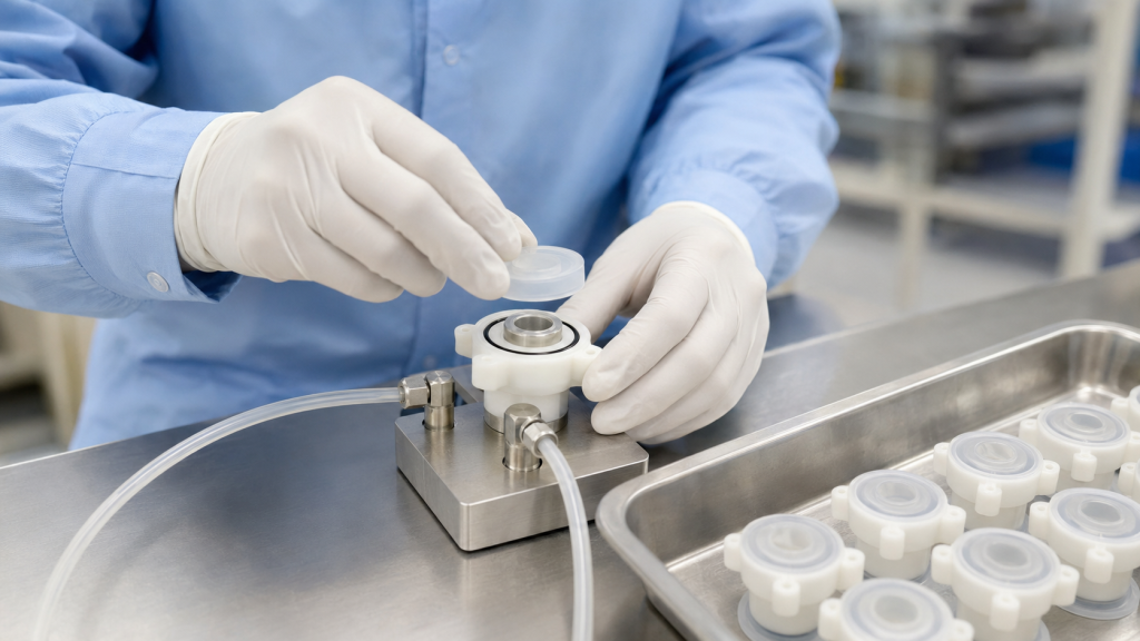
シリコーン部品のアセンブリが難しい理由
シリコーンゴムは、柔軟性、耐熱性、優れたシール性能を備えていますが、これらの特性そのものが組み立て上の課題をもたらしています。.
よくある課題としては、次のようなものがあります:
- 接着を妨げる低い表面エネルギー
- 位置決め中に変形する柔軟な部品
- シール部の周囲における可変圧縮
- 離型剤の残留物または汚染
- シリコーンと硬質基板との間の熱膨張率の違い
- 露出した接合部の端部における高い剥離応力
- オーバーモールド時のインサートの動き
- 薄いシリコーン断面を通るガス透過性
- 据付部からの漏れと製品からの漏れを区別するのが難しい
最初の設計上の判断は、その接合部に化学的接着、機械的保持、あるいはその両方が必要かどうかという点である。.
主なシリコーンの組み立て方法
| 方法 | 代表的な用途 | 主な利点 | 主な制限事項 |
|---|---|---|---|
| シリコーン接着 | シリコーン同士、あるいはシリコーンと金属またはプラスチックとの組み立て | 柔軟で連続した接合部 | 表面処理および硬化が必要 |
| プライマーを用いた接着 | 加工が困難なプラスチック、金属、またはガラスの基材 | 界面の密着性を向上させる | 追加の制御工程 |
| 自己接着型LSRオーバーモールド | シリコーンからプラスチックまたは金属への大量生産部品 | 自動化された統合組立 | 材料の適合性を検証する必要があります |
| 機械式インターロック | ガスケット、ハウジング、インサート、およびケーブル部品 | 化学だけに依存しているわけではない | 追加の形状設計および金型が必要となります |
| 圧縮キャプチャ | シール、ダイヤフラム、および交換用ガスケット | シンプルで実用的 | 圧縮は適切に制御されなければならない |
| 化学的・機械的ハイブリッド接合 | 重要なシールおよび構造アセンブリ | 冗長な保持 | さらなる設計および検証作業 |
| 締結部品、クランプ、または圧着 | チューブ、ハウジング、および現場で整備可能なアセンブリ | 点検や分解が容易 | 局所的なシリコーン損傷のリスク |
1. シリコーン系接着剤による接着
接着接合は、成形後に別々に製造された部品を接合する工程です。組み立て内容に応じて、接着剤としては、1液型のRTVシリコーン、2液型のシリコーン接着剤、あるいはその他の適合する柔軟性のある接着剤システムが使用されます。.
シリコーンとシリコーンの接合
両方の部品がシリコーンゴムである場合、シリコーン系接着剤がよく使用されます。適切に選定された接着剤を使用すれば、成形部品とともに動く柔軟な接合部を形成することができます。.
代表的な用途としては、次のようなものがあります:
- 成形コネクタへのシリコンチューブの接続
- バルブ部品の接合
- 柔軟な本体へのシリコーンシール取り付け
- 成形シリコーンアセンブリの修理または閉鎖
- 硬度の異なる2種類のシリコーンの接合
表面は清潔で、油分、ほこり、未硬化の材料、離型剤の残留物などが一切ない状態である必要があります。また、一部の硬化したシリコーン表面については、プラズマ処理、コロナ処理、またはプライマー処理が必要となる場合があります。.
シリコーンとプラスチックの接合
シリコーンと熱可塑性樹脂の接着は、接着性が使用する樹脂の種類、添加剤、ガラス繊維の含有量、および表面の状態に左右されるため、より困難になる場合があります。.
重要な変数には、次のようなものがあります:
- 正確なポリマーグレード
- 水分含有量
- 離型剤
- 表面の質感
- 耐熱性
- 接着剤の硬化条件
- 使用中の化学物質への曝露
あるポリカーボネートまたはナイロンのグレード向けに開発された接着剤は、他のグレードでも自動的に機能するとは限らない。.
シリコーンと金属の接合
金属インサートには、通常、切削油、酸化物、ほこり、指紋が付着していないことが求められます。脱脂、制御された表面粗化処理、プラズマ処理、あるいはプライマー塗布が必要となる場合があります。.
適切な基材としては、以下が挙げられる:
- ステンレス鋼
- アルミニウム
- 真鍮
- 銅合金
- コーティング処理された金属部品
- 金属製ケーブル端子
- センサーハウジング
また、サプライヤーは、金属コーティング、メッキ、または不動態化層によって密着性が変化するかどうかを評価すべきである。.
表面処理
表面処理には、以下のようなものがあります:
- 洗浄および脱脂
- 乾燥
- プラズマ処理、コロナ処理、または火炎処理
- 下塗りの施工
- 制御された接着剤の塗布
- 治具
- 硬化
- ボンド検査
WACKER社は、シリコーンの密着性は基材の種類や機械的負荷によって異なり、組み合わせによってはプライマー処理、プラズマ処理、またはコロナ処理が必要になる場合があるとしている。(WACKER シリコーン接着に関するガイダンス)
表面処理の効果は徐々に低下する可能性があるため、処理から接着までの最大許容時間を検証し、製造指示書に記載する必要があります。.
2. 自己接着型LSRオーバーモールド
自己接着性液体シリコーンゴムは、射出成形時に特定の熱可塑性樹脂、金属、その他の基材に接着するよう配合されています。.
剛性部品には、次のようなものがあります:
- LSR金型に挿入し、オーバーモールド加工を施す
- 2成分金型の第1ステーションで成形される
- 自動的に第2の成形ステーションへ移送される
- 金属製またはプラスチック製の既製インサートとして組み込まれている
一部の自己接着性LSRグレードは、プライマーやプラズマ処理を施さなくても、特定の基材に接着することができます。例えば、WACKER社は、2液成形においてポリカーボネートへの接着を目的として開発された自己接着性LSRについて説明しています。(WACKERの自己接着性LSRの事例)
しかし、「自己接着」は万能な接着を意味するわけではありません。接着性は、正確に以下の条件を用いて試験しなければなりません:
- LSRグレード
- 基材樹脂または金属
- 着色剤および添加剤
- 基板の成形条件
- 表面仕上げ
- 保管条件
- オーバーモールド温度
- 硬化時間
- 環境曝露
自己接着型オーバーモールドの利点
- 二次組立の削減
- 手作業による接着剤の塗布が不要になります
- 大量処理の自動化に対応
- 連続的なシール面を形成する
- ばらばらの部品の数を減らします
- 部品の位置決め精度を向上させる
- 異なる色や硬度を組み合わせることができます
- 一体型ガスケットおよび保護カバーに対応しています
潜在的なリスク
- 成形熱による基板の変形
- 湿気による接着力の低下
- 相容れない材料による硬化阻害
- 注入中の挿入動作
- ロック機構の背後にシリコーンが十分に流れ込んでいない
- 汚染に起因する付着性のばらつき
- 目に見えない接着箇所の検査が困難
基材は、LSR成形工程において、反りや溶融が生じず、また硬化を妨げる物質を放出することなく、この工程に耐えられなければならない。.
3. 機械式ロック
機械的ロック機構は、化学的接着のみに頼るのではなく、形状によってシリコーンを固定します。.
一般的な機械式ロック機能には、次のようなものがあります:
- 貫通穴
- 座ぐり穴
- アンダーカット
- ダブテール溝
- 保持リブ
- 周方向の溝
- フランジ
- T字型チャンネル
- 穴あきインサート
- キャプチャされたエッジ
- 逆テーパー状の溝
- 成形リテンションビーズ
オーバーモールド成形では、LSRがこれらの形状内部や周囲を流れ、硬化すると、変形や破断なしには取り外せない形状になります。.
プロトラブスは、アンダーカット、逆テーパー穴、座ぐりなどの構造を活用し、多くのオーバーモールド組立品において、化学的結合を補完または代替する手段として、機械的インターロックを推奨しています。(Protolabsのオーバーモールド設計ガイドライン)
機械式ロックの利点
- 基板表面の化学的性質への依存度が低い
- 目に見えて予測可能な保持効果をもたらします
- 化学的相容性の低い材料に対応しています
- 剥離力や引き抜き力に対する耐性を向上させることができる
- ある程度の環境老化を経てもその効果は持続する
- プライマーや接着剤が不要になる場合があります
機械式ロック機構の設計原則
負荷を分散させる
いくつかの小さな固定部を設ける方が、1つの大きなアンカーよりも応力をより均等に分散させることができる場合があります。応力が一点に集中すると、インサート周辺の柔らかいシリコーンが破れる恐れがあります。.
鋭い角を避ける
基板の縁が鋭利だと、シリコーンを切断したり、破れを引き起こしたりする恐れがあります。シリコーンが硬質部品の周囲で伸びる部分には、丸みを付ける必要があります。.
シリコーンを十分に塗布する
穴、溝、またはアンダーカットを囲むシリコーンは、引き裂きに耐えられる十分な厚さである必要があります。極端に薄い部分については、充填は正しく行われていても、引張試験の際に破断する可能性があります。.
LSRの流動とベントについて検討する
機械式ロック機構の背後に空気が閉じ込められることがあります。ゲートの配置と通気口の設定は、LSRがインターロック全体を完全に充填できるようにする必要があります。.
コントロール・インサート位置
金型を閉じて射出成形を行う間、インサートは安定した状態を保たなければなりません。位置決めピン、固定具、あるいはロボットによる装填機能が必要となる場合があります。.
重要なシール面からインターロックを遠ざけてください
機械的なロック機構は、隣接するシール面の圧縮状態や平坦性を損なってはならない。.
4. 圧縮キャプチャ
圧縮固定とは、シリコーン製のガスケットやダイヤフラムを、剛性のある部品間に挟み込みつつ、恒久的に接着することなく固定する手法です。.
例としては、次のようなものがあります:
- ハウジングの溝に嵌め込まれたガスケット
- 2枚のプラスチックカバーの間に挟み込まれたダイヤフラム
- 機械加工されたグランドに保持されたOリング
- 剛性フレームで固定されたシリコーン膜
- ネジで締め付けられた着脱可能なシール
メリット
- シール交換が可能
- 接着剤の適合性の問題を回避します
- 材料の認定手続きを簡素化します
- シール圧縮を直接制御します
- 二次硬化や接着作業を削減できる
設計上のリスク
- 過度な圧縮は、シリコーンを損傷させたり、永久的な変形を引き起こしたりする恐れがあります
- 圧縮が不十分だと、漏れの原因となる可能性があります
- ファスナーへの荷重が不均一になると、局所的な隙間が生じる可能性があります
- ガスケットが回転したり、ねじれたり、あるいは溝から外れたりする可能性があります
- ハウジングの鋭いエッジによってシールが切れてしまう可能性があります
- 寸法の積み重ねにより、圧縮率が変化する可能性があります
締め付けは、作業者がかける締め付けトルクだけでなく、溝の深さ、ガスケットの厚さ、ハードストップ、あるいは剛性スペーサーなどを通じて制御すべきである。.
5. 締結部品、クランプ、および圧着
一部のシリコーンアセンブリでは、以下のものが使用されています:
- 金属製またはプラスチック製のクランプ
- 圧着スリーブ
- ねじ込み式ハウジング
- スナップフィット式リテーナー
- ケーブル用ストレインリリーフカラー
- 保持リング
- 外部フレーム
これらの方法は、アセンブリの修理が可能でなければならない場合や、基板上に直接成形することが現実的でない場合に適している可能性があります。.
締結具は、柔らかいシリコーンに直接押し込むのではなく、剛性のあるフレーム、ワッシャー、または圧縮プレートに荷重をかけるようにしてください。締結具の圧力が一点に集中すると、切り込み、クリープ、または押し出しが生じるおそれがあります。.
圧着接続については、以下の点について検証を行う必要があります:
- 引き抜き力
- シリコーン製コンプレッション
- 鋭い金属の縁
- 寸法公差
- 振動
- 温度サイクル試験
- 流体への曝露
- 長期的なリラクゼーション
6. 化学的および機械的なハイブリッド組立
重要な用途では、化学結合と機械的ロックが併用されることがよくあります。.
ハイブリッドジョイントには、以下のものが含まれる場合がある:
- 自己接着型LSRと貫通穴の組み合わせ
- プライマーを用いた接着とアンダーカットの併用
- シリコーン系接着剤と圧縮用溝
- オーバーモールド加工に加え、剛性のある保持フランジ
- 接着接合と圧着カラーの併用
化学結合により、液体の移動や端部の浮き上がりを防ぐ一方で、機械的特性によって補強による保持力を確保します。.
ハイブリッド構造は、特に以下の状況下にある接合部において有用です:
- ピールの装填
- 繰り返しの屈伸
- 振動
- 熱サイクル
- 内圧
- 洗浄用化学薬品
- 滅菌
- 長寿命
ただし、制御されていない接着工程を隠蔽するために、機械的なインターロックを使用してはならない。両方の保持機構については、実用上可能な限り、それぞれ個別に検証を行うべきである。.
組み立て方法の比較
| 要件 | 接着接合 | 自己接着型オーバーモールド | 機械式ロック | 圧縮キャプチャ |
| Low production volume | 素晴らしい | 数量限定 | いい | 素晴らしい |
| High production volume | Moderate | 素晴らしい | 素晴らしい | いい |
| Permanent assembly | はい | はい | Usually | No |
| Replaceable seal | Poor | Poor | 数量限定 | 素晴らしい |
| Difficult material combination | Primer may help | Grade-dependent | 素晴らしい | 素晴らしい |
| Continuous fluid barrier | いい | 素晴らしい | Requires sealing geometry | いい |
| High peel resistance | 設計に依存する | 設計に依存する | いい | Not applicable |
| 初期金型費 | 低 | 高い | Medium to high | 中 |
| Process automation | Moderate | 素晴らしい | 素晴らしい | いい |
Assembly Process Controls
A reliable assembly process should define more than the adhesive name or molding machine setting.
重要な制御項目には、以下のものが含まれます:
- Material and substrate lot identification
- Incoming substrate inspection
- 洗浄方法
- Surface-treatment parameters
- Maximum time after treatment
- Adhesive mix ratio
- Dispensing volume
- Bond-line location and thickness
- Fixture pressure
- Cure temperature and time
- 挿入位置
- Overmolding cavity identification
- 視覚的受け入れ基準
- Pull or peel-test frequency
- Leak-test settings
- 包装および保管条件
For adhesive systems, the manufacturer’s recommended curing conditions should be validated using the actual assembly because large metal inserts and plastic housings can change heat transfer.
Evaluating Bond Strength
The test method should reproduce the expected loading direction.
Pull-Out Testing
Used for inserts, connectors, cables and tubes. The part is pulled axially until reaching a specified force or failure.
ピール試験
Useful where an exposed silicone edge may lift from a rigid substrate. Peel testing is often more demanding than a straight shear test.
Shear Testing
Measures resistance when the bonded materials move parallel to the joint.
Torque Testing
Suitable for rotating connectors, threaded inserts and handles.
Burst or Proof-Pressure Testing
Verifies that a sealed assembly can withstand a specified pressure without separation or permanent damage.
Cyclic Durability Testing
The component may be repeatedly bent, compressed, twisted or pressurized to evaluate fatigue performance.
The failure mode should be recorded:
- Adhesive failure at the interface
- Cohesive failure inside the adhesive
- シリコーンの破れ
- Substrate failure
- Mechanical interlock pull-out
- Insert deformation
A high force value is not sufficient if the failure occurs unpredictably or damages a critical functional area.
Why Leak Testing Is Important
A joint can look fully assembled and still contain a microscopic leak path. Leakage may occur through:
- Incomplete adhesive coverage
- Air bubbles in the bond line
- Poor wetting of the substrate
- Flash on a sealing surface
- 挿入の動き
- Insufficient gasket compression
- 表面の傷
- Cracks in a rigid housing
- 汚染
- Incomplete mechanical engagement
Leak testing should be selected according to the service medium, required sensitivity, part volume, test cycle and whether the test must locate or only detect a leak.
Pressure Decay Leak Testing
In pressure decay testing, the assembly is filled with air or another test gas to a controlled pressure. The source is isolated, the system stabilizes and the instrument measures the pressure loss during a defined test period.
Cincinnati Test Systems describes pressure decay as pressurizing the test part, isolating it and measuring pressure loss over time. (CTS leak-testing methods)
対象:
- Closed silicone-plastic housings
- 流体用コネクタ
- バルブアセンブリ
- Waterproof electronic components
- Tubing assemblies
- Overmolded sensors
メリット:
- Non-destructive
- Suitable for production automation
- Does not require expensive tracer gas
- Provides quantitative pass/fail data
制限事項:
- Temperature changes influence pressure
- Flexible silicone can expand during filling
- Large internal volumes increase test time
- Fixture leakage may be mistaken for product leakage
- Gas permeation through thin silicone may affect long tests
A stabilization period is particularly important for flexible silicone assemblies because the part may expand slightly after pressurization.
真空劣化試験
Vacuum decay testing evacuates the internal volume and measures the subsequent pressure rise. The principle is similar to pressure decay, but the test part is exposed to vacuum rather than positive internal pressure.
対象:
- Components used under vacuum
- Closed cavities that may deform under pressure
- Assemblies where outward pressurization could disturb the seal
- Selected medical and fluid-handling parts
The designer should confirm that vacuum does not collapse thin silicone walls or pull a flexible valve into an unintended position.
Mass Flow Leak Testing
Mass flow testing supplies air while measuring the flow required to maintain a specified pressure.
対象:
- Parts with a defined permitted flow
- Larger leakage rates
- Valves and regulators
- Components where cycle time is important
- Assemblies with stable internal volume
Mass flow testing can provide a direct flow-related result, but the system must distinguish intended flow paths from unintended leakage.
Tracer-Gas Leak Testing
Tracer-gas testing uses helium or a hydrogen-containing forming gas. The gas passes through a leak and is detected using a dedicated sensor.
Pfeiffer describes tracer-gas methods as suitable for detecting and quantifying very small leaks. Sniffer testing is generally used for pressurized components, while spray or vacuum-chamber methods can be used for evacuated parts. (Pfeiffer leak-detection methods)
対象:
- Very low allowable leakage
- Critical medical, semiconductor or electronic assemblies
- High-value components
- Leak localization
- Engineering validation
- Development of new sealing designs
メリット:
- High sensitivity
- Can locate the leaking area
- Quantitative results are possible
- Useful for validating other production tests
制限事項:
- Higher equipment and gas cost
- Requires background-gas control
- Fixture design is more complex
- Gas conversion may be needed when comparing the test medium with the service fluid
気泡漏れ試験
The assembly is pressurized and placed in liquid or coated with a leak-detection solution. Bubbles indicate escaping gas.
Bubble testing is simple and useful for troubleshooting, but it is generally operator-dependent and may not provide a precise leak-rate value.
It is better suited to engineering analysis or leak localization than tightly controlled automated production.
Designing a Reliable Leak Test
A leak-test specification should define:
- Test medium
- Test pressure or vacuum
- 時間をつぶす
- 安定化時間
- Measurement time
- Maximum allowable leak rate
- 温度範囲
- Test direction
- Fixture sealing points
- 部品の向き
- 合格・不合格の基準
- Calibration method
- Master good and master reject parts
- Data-recording requirement
Control Fixture Leakage
The fixture must seal outside the area being evaluated. Otherwise, the test measures the fixture instead of the assembly.
Allow for Silicone Deformation
Flexible silicone may expand, compress or relax during the test. Stabilization time and fixture support should be established experimentally.
Consider Permeation
Gas may slowly permeate through thin silicone even when no physical leak path is present. Test time, pressure and allowable limit should distinguish actual assembly leakage from material behavior.
Test in the Correct Direction
A seal may perform differently when pressure is applied from the opposite side. One-way valves and lip seals must be tested in the intended service direction.
Use Known Leak Standards
Calibrated leak standards and validated reference parts help confirm that the test system can reliably detect the specified defect.
Common Assembly Failures
| 失敗 | 考えられる原因 | Recommended Review |
| Silicone separates from plastic | Contamination, incompatible material or insufficient treatment | Verify resin grade, cleaning and surface activation |
| インサートが引き出される | Insufficient bond area or weak interlock | Add through-holes, undercuts or retention ribs |
| Joint leaks after aging | Fluid exposure, thermal cycling or adhesive degradation | Conduct environmental and accelerated aging tests |
| Silicone tears near insert | Sharp edge or concentrated load | Add radii and increase silicone coverage |
| Leak results are unstable | Temperature drift or flexible-part expansion | Improve stabilization and fixture support |
| Good parts fail leak testing | Fixture leakage or overly long test time | Validate fixture and evaluate permeation |
| Bond varies by batch | Substrate, adhesive or surface-treatment variation | Improve incoming control and traceability |
| Air bubbles in bond line | Poor dispensing or assembly technique | Control dispensing path, volume and fixturing |
What to Include in a Silicone Assembly RFQ
Provide the following information:
- 2D図面および3Dモデル
- Silicone material and hardness
- Exact plastic or metal substrate grade
- Joint and sealing requirements
- Expected loading direction
- Critical surface map
- Bonding restrictions
- Allowed primers or surface treatments
- Annual and batch quantity
- Service temperature
- 液体および化学物質への曝露
- Sterilization or cleaning method
- Required pull, peel or torque force
- Test pressure or vacuum
- Maximum allowable leak rate
- Proof or burst-pressure requirement
- Required inspection records
- 包装および清潔さに関する要件
結論
There is no single assembly method suitable for every silicone component.
Adhesive bonding provides a flexible continuous joint and works well for prototypes and low-volume assemblies. Self-bonding LSR overmolding supports automated production and integrated sealing. Mechanical interlocks provide reliable retention when chemical bonding is uncertain. Compression capture is often best for replaceable seals, while hybrid joints offer additional protection in demanding applications.
The final assembly should be validated through mechanical testing, environmental aging and an appropriate leak-test method. Pressure decay and vacuum decay are widely used for production testing, mass flow is useful for flow-based acceptance, and tracer gas provides greater sensitivity for critical assemblies.
FHY Silicone provides custom silicone molding, LSR overmolding, insert molding, component assembly and leak-testing support. Send us your drawing, substrate information, required leak rate and expected production volume for a manufacturability review.
よくある質問
What is the best way to bond silicone to plastic?
The best method depends on the exact plastic grade, silicone formulation and operating environment. Options include self-bonding LSR, silicone adhesive, primer-assisted bonding and plasma treatment. Testing with the actual production materials is essential.
Can mechanical locking replace silicone adhesive?
Yes, in some designs. Through-holes, undercuts, counterbores and grooves can provide strong retention. However, a mechanical lock may not provide a continuous fluid barrier unless combined with compression or chemical adhesion.
Why combine chemical bonding with a mechanical interlock?
The chemical bond helps seal the interface, while the interlock provides backup retention against peel, vibration and pull-out loads.
Which leak test is suitable for silicone assemblies?
Pressure decay is commonly used for sealed assemblies. Vacuum decay may be better for vacuum-service parts, while tracer-gas testing is suitable for very low leak-rate requirements.
Can silicone permeability affect leak-test results?
Yes. Thin silicone sections may allow gradual gas permeation, particularly during long tests. The test method should distinguish material permeation from an actual assembly leak.
How can insert pull-out be prevented?
Increase the bonding area, add radii, use holes or undercuts, provide adequate silicone coverage and consider combining mechanical locking with self-bonding LSR.
Should every assembled part be leak tested?
It depends on the application, risk level and production agreement. Critical fluid, medical, waterproof or pressure-containing assemblies often require 100% production leak testing.
 English
  Japanese
  Korean
  German
  French
  Italian
  Spanish
  Dutch
Dutch  Chinese
  Portuguese
  Polish
  Czech
Czech  Hungarian
  Swedish
  Finnish
  Vietnamese
  Thai
Thai  Turkish
  Arabic
  Russian