
A molded silicone component is often only one part of a larger assembly. It may need to connect to a plastic housing, metal insert, cable, sensor, valve, tube or another silicone part. The assembly must remain secure while also meeting requirements for sealing, flexibility, cleanliness and long-term durability.
Selecting the wrong joining method can result in adhesive separation, silicone tearing, insert movement or leakage during use. A reliable design therefore considers the joint geometry, material combination, loading direction, manufacturing process and inspection method from the beginning.
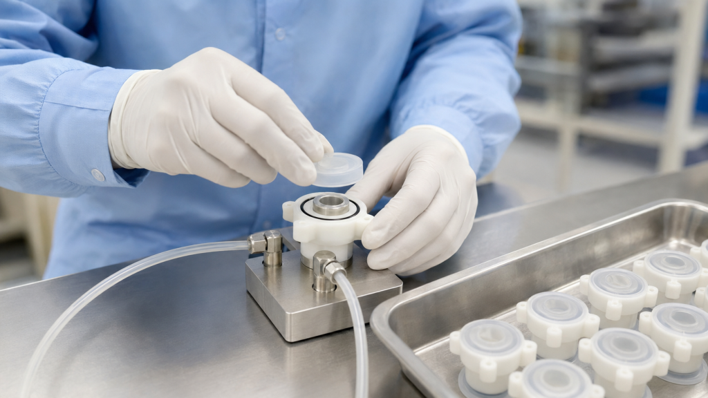
This guide compares silicone bonding, mechanical locking and hybrid assembly methods, then explains how pressure decay, vacuum decay, mass flow and tracer-gas testing can be used to verify sealing performance.
Why Silicone Components Are Difficult to Assemble
Silicone rubber provides flexibility, temperature resistance and good sealing performance, but these same characteristics create assembly challenges.
Common difficulties include:
- Low surface energy that limits adhesion
- Flexible parts that deform during positioning
- Variable compression around sealing areas
- Mold-release residue or contamination
- Different thermal expansion between silicone and rigid substrates
- High peel stress at exposed joint edges
- Movement of inserts during overmolding
- Gas permeability through thin silicone sections
- Difficulty distinguishing fixture leakage from product leakage
The first design decision is whether the joint needs chemical adhesion, mechanical retention or both.
Main Silicone Assembly Methods
| Method | Typical Application | Main Advantage | Main Limitation |
|---|---|---|---|
| Silicone adhesive bonding | Silicone-to-silicone, metal or plastic assembly | Flexible, continuous joint | Surface preparation and curing required |
| Primer-assisted bonding | Difficult plastic, metal or glass substrates | Improves interfacial adhesion | Additional controlled process step |
| Self-bonding LSR overmolding | High-volume silicone-to-plastic or metal components | Automated integrated assembly | Material compatibility must be validated |
| Mechanical interlocking | Gaskets, housings, inserts and cable components | Does not rely entirely on chemistry | Requires additional geometry and tooling |
| Compression capture | Seals, diaphragms and replaceable gaskets | Simple and serviceable | Compression must remain controlled |
| Hybrid chemical-mechanical joint | Critical sealing and structural assemblies | Redundant retention | More design and validation work |
| Fasteners, clamps or crimping | Tubes, housings and field-serviceable assemblies | Easy to inspect or disassemble | Risk of local silicone damage |
1. Silicone Adhesive Bonding
Adhesive bonding joins separately manufactured components after molding. Depending on the assembly, the adhesive may be a one-part RTV silicone, two-part silicone adhesive or another compatible flexible adhesive system.
Silicone-to-Silicone Bonding
Silicone adhesives are frequently used when both components are silicone rubber. A properly selected adhesive can create a flexible joint that moves with the molded components.
Tipik kullanım alanları şunlardır:
- Joining silicone tubes to molded connectors
- Bonding valve components
- Attaching silicone seals to flexible bodies
- Repairing or closing molded silicone assemblies
- Bonding two different silicone hardnesses
The surfaces must be clean and free from oil, dust, uncured material and mold-release residue. Some cured silicone surfaces may also require plasma, corona or primer treatment.
Silicone-to-Plastic Bonding
Bonding silicone to thermoplastics can be more difficult because adhesion depends on the specific resin, additives, glass-fiber content and surface condition.
Önemli değişkenler şunlardır:
- Exact polymer grade
- Moisture content
- Mold-release additives
- Yüzey dokusu
- Heat resistance
- Adhesive curing conditions
- Chemical exposure during use
A bond developed for one polycarbonate or nylon grade should not automatically be assumed to work with another grade.
Silicone-to-Metal Bonding
Metal inserts should normally be free from machining oil, oxidation, dust and fingerprints. Degreasing, controlled surface roughening, plasma treatment or primer may be required.
Suitable substrates may include:
- Stainless steel
- Aluminum
- Brass
- Copper alloys
- Coated metal parts
- Metal cable terminals
- Sensör muhafazaları
The supplier should also evaluate whether the metal coating, plating or passivation layer changes adhesion.
Yüzey Hazırlığı
Surface preparation may include:
- Cleaning and degreasing
- Drying
- Plasma, corona or flame treatment
- Primer application
- Controlled adhesive dispensing
- Fixturing
- Curing
- Bond inspection
WACKER notes that silicone adhesion depends on substrate type and mechanical loading, and that primers, plasma or corona treatment may be required for some combinations. (WACKER silicone adhesion guidance)
Surface activation may gradually lose effectiveness, so the maximum allowable time between treatment and bonding should be validated and included in the production instructions.
2. Self-Bonding LSR Overmolding
Self-bonding liquid silicone rubber is formulated to adhere to selected thermoplastics, metals or other substrates during injection molding.
The rigid component may be:
- Inserted into an LSR mold and overmolded
- Produced in the first station of a two-component mold
- Transferred automatically to a second molding station
- Loaded as a prefabricated metal or plastic insert
Some self-bonding LSR grades can bond to selected substrates without primer or plasma treatment. For example, WACKER describes a self-adhesive LSR developed for bonding to polycarbonate in two-component molding. (WACKER self-bonding LSR example)
However, “self-bonding” does not mean universal bonding. Adhesion must be tested using the exact:
- LSR grade
- Substrate resin or metal
- Colorant and additives
- Substrate molding conditions
- Yüzey işleme
- Storage conditions
- Overmolding temperature
- Cure time
- Environmental exposure
Advantages of Self-Bonding Overmolding
- Reduces secondary assembly
- Eliminates manual adhesive dispensing
- Supports high-volume automation
- Produces a continuous sealing interface
- Reduces the number of loose components
- Improves part positioning
- Can combine different colors or hardnesses
- Supports integrated gaskets and protective covers
Potential Risks
- Substrate deformation under molding heat
- Moisture-related adhesion loss
- Cure inhibition from incompatible materials
- Insert movement during injection
- Incomplete silicone flow behind locking features
- Adhesion variation caused by contamination
- Difficult inspection of hidden bond areas
The substrate must tolerate the LSR molding process without warping, melting or releasing substances that interfere with curing.
3. Mechanical Locking
Mechanical locking retains the silicone through geometry instead of relying only on chemical adhesion.
Common mechanical locking features include:
- Through-holes
- Counterbored holes
- Undercuts
- Dovetail grooves
- Retention ribs
- Circumferential grooves
- Flanges
- T-shaped channels
- Perforated inserts
- Captured edges
- Reverse-tapered slots
- Molded retention beads
During overmolding, LSR flows through or around these features and cures into a shape that cannot be removed without deformation or tearing.
Protolabs recommends mechanical interlocks to supplement or replace chemical bonding in many overmolded assemblies, using features such as undercuts, reverse-tapered holes and counterbores. (Protolabs overmolding design guidance)
Advantages of Mechanical Locking
- Less dependent on substrate surface chemistry
- Provides visible and predictable retention
- Supports materials with poor chemical compatibility
- Can improve resistance to peel and pull-out forces
- Remains effective after some environmental aging
- May eliminate primers or adhesives
Mechanical Locking Design Principles
Distribute the Load
Several small retention features may distribute stress more evenly than one large anchor. Concentrated stress can tear soft silicone around an insert.
Avoid Sharp Corners
Sharp substrate edges may cut or initiate tearing in the silicone. Radii should be added where the silicone stretches around the rigid component.
Provide Adequate Silicone Coverage
The silicone surrounding a hole, groove or undercut must be thick enough to resist tearing. Extremely thin ligaments may fill correctly but fail during pull testing.
Consider LSR Flow and Venting
Air can become trapped behind mechanical locking features. Gate placement and venting must allow LSR to fill the complete interlock.
Control Insert Position
The insert must remain stable during mold closing and injection. Locating pins, fixtures or robot-loading features may be required.
Keep Interlocks Away from Critical Sealing Lands
Mechanical locking features should not distort the compression or flatness of a nearby sealing surface.
4. Compression Capture
Compression capture holds a silicone gasket or diaphragm between rigid components without permanently bonding it.
Örnekler şunlardır:
- A gasket captured in a housing groove
- A diaphragm clamped between two plastic covers
- An O-ring retained in a machined gland
- A silicone membrane held by a rigid frame
- A removable seal compressed by screws
Avantajlar
- Allows seal replacement
- Avoids adhesive compatibility issues
- Simplifies material qualification
- Provides direct control of sealing compression
- Can reduce secondary curing and bonding operations
Design Risks
- Excessive compression can damage or permanently deform the silicone
- Insufficient compression can cause leakage
- Uneven fastener loading can create local gaps
- The gasket may roll, twist or escape from the groove
- Sharp housing edges may cut the seal
- Dimensional stack-up may change compression
Compression should be controlled through groove depth, gasket thickness, hard stops or rigid spacers—not only through operator-applied tightening torque.
5. Fasteners, Clamps and Crimping
Some silicone assemblies use:
- Metal or plastic clamps
- Crimp sleeves
- Threaded housings
- Snap-fit retainers
- Cable strain-relief collars
- Tespit halkaları
- External frames
These methods may be suitable when the assembly must be serviceable or when molding directly onto the substrate is not practical.
Fasteners should load a rigid frame, washer or compression plate rather than pressing directly into soft silicone. Concentrated fastener pressure may cause cutting, creep or extrusion.
Crimped connections must be validated for:
- Çekme kuvveti
- Silicone compression
- Sharp metal edges
- Dimensional variation
- Vibration
- Temperature cycling
- Fluid exposure
- Long-term relaxation
6. Hybrid Chemical and Mechanical Assembly
For critical applications, chemical bonding and mechanical locking are often used together.
A hybrid joint may include:
- Self-bonding LSR plus through-holes
- Primer-assisted bonding plus an undercut
- Silicone adhesive plus a compression groove
- Overmolding plus a rigid retaining flange
- Adhesive bonding plus a crimp collar
The chemical bond helps prevent fluid migration and edge lifting, while the mechanical feature provides backup retention.
Hybrid construction is especially useful where the joint experiences:
- Peel loading
- Repeated flexing
- Vibration
- Termal döngü
- Internal pressure
- Cleaning chemicals
- Sterilization
- Uzun hizmet ömrü
However, a mechanical interlock should not be used to hide an uncontrolled bonding process. Both retention mechanisms should be validated separately where practical.
Comparing Assembly Methods
| Requirement | Adhesive Bonding | Self-Bonding Overmolding | Mechanical Locking | Compression Capture |
| Low production volume | Excellent | Limited | Good | Excellent |
| High production volume | Moderate | Excellent | Excellent | Good |
| Permanent assembly | Evet | Evet | Usually | No |
| Replaceable seal | Poor | Poor | Limited | Excellent |
| Difficult material combination | Primer may help | Grade-dependent | Excellent | Excellent |
| Continuous fluid barrier | Good | Excellent | Requires sealing geometry | Good |
| High peel resistance | Design-dependent | Design-dependent | Good | Not applicable |
| Initial tooling cost | Low | Yüksek | Medium to high | Medium |
| Process automation | Moderate | Excellent | Excellent | Good |
Assembly Process Controls
A reliable assembly process should define more than the adhesive name or molding machine setting.
Important controls include:
- Material and substrate lot identification
- Incoming substrate inspection
- Temizleme yöntemi
- Surface-treatment parameters
- Maximum time after treatment
- Adhesive mix ratio
- Dispensing volume
- Bond-line location and thickness
- Fixture pressure
- Cure temperature and time
- Ekleme konumu
- Overmolding cavity identification
- Visual acceptance criteria
- Pull or peel-test frequency
- Leak-test settings
- Packaging and storage conditions
For adhesive systems, the manufacturer’s recommended curing conditions should be validated using the actual assembly because large metal inserts and plastic housings can change heat transfer.
Evaluating Bond Strength
The test method should reproduce the expected loading direction.
Pull-Out Testing
Used for inserts, connectors, cables and tubes. The part is pulled axially until reaching a specified force or failure.
Peel Testing
Useful where an exposed silicone edge may lift from a rigid substrate. Peel testing is often more demanding than a straight shear test.
Shear Testing
Measures resistance when the bonded materials move parallel to the joint.
Torque Testing
Suitable for rotating connectors, threaded inserts and handles.
Burst or Proof-Pressure Testing
Verifies that a sealed assembly can withstand a specified pressure without separation or permanent damage.
Cyclic Durability Testing
The component may be repeatedly bent, compressed, twisted or pressurized to evaluate fatigue performance.
The failure mode should be recorded:
- Adhesive failure at the interface
- Cohesive failure inside the adhesive
- Silicone tearing
- Substrate failure
- Mechanical interlock pull-out
- Insert deformation
A high force value is not sufficient if the failure occurs unpredictably or damages a critical functional area.
Why Leak Testing Is Important
A joint can look fully assembled and still contain a microscopic leak path. Leakage may occur through:
- Incomplete adhesive coverage
- Air bubbles in the bond line
- Poor wetting of the substrate
- Flash on a sealing surface
- Insert movement
- Insufficient gasket compression
- Yüzey çizikleri
- Cracks in a rigid housing
- Kirlenme
- Incomplete mechanical engagement
Leak testing should be selected according to the service medium, required sensitivity, part volume, test cycle and whether the test must locate or only detect a leak.
Pressure Decay Leak Testing
In pressure decay testing, the assembly is filled with air or another test gas to a controlled pressure. The source is isolated, the system stabilizes and the instrument measures the pressure loss during a defined test period.
Cincinnati Test Systems describes pressure decay as pressurizing the test part, isolating it and measuring pressure loss over time. (CTS leak-testing methods)
Uygun olduğu durumlar:
- Closed silicone-plastic housings
- Fluid connectors
- Valf grupları
- Waterproof electronic components
- Tubing assemblies
- Overmolded sensors
Advantages:
- Non-destructive
- Suitable for production automation
- Does not require expensive tracer gas
- Provides quantitative pass/fail data
Limitations:
- Temperature changes influence pressure
- Flexible silicone can expand during filling
- Large internal volumes increase test time
- Fixture leakage may be mistaken for product leakage
- Gas permeation through thin silicone may affect long tests
A stabilization period is particularly important for flexible silicone assemblies because the part may expand slightly after pressurization.
Vacuum Decay Testing
Vacuum decay testing evacuates the internal volume and measures the subsequent pressure rise. The principle is similar to pressure decay, but the test part is exposed to vacuum rather than positive internal pressure.
Uygun olduğu durumlar:
- Components used under vacuum
- Closed cavities that may deform under pressure
- Assemblies where outward pressurization could disturb the seal
- Selected medical and fluid-handling parts
The designer should confirm that vacuum does not collapse thin silicone walls or pull a flexible valve into an unintended position.
Mass Flow Leak Testing
Mass flow testing supplies air while measuring the flow required to maintain a specified pressure.
Uygun olduğu durumlar:
- Parts with a defined permitted flow
- Larger leakage rates
- Valves and regulators
- Components where cycle time is important
- Assemblies with stable internal volume
Mass flow testing can provide a direct flow-related result, but the system must distinguish intended flow paths from unintended leakage.
Tracer-Gas Leak Testing
Tracer-gas testing uses helium or a hydrogen-containing forming gas. The gas passes through a leak and is detected using a dedicated sensor.
Pfeiffer describes tracer-gas methods as suitable for detecting and quantifying very small leaks. Sniffer testing is generally used for pressurized components, while spray or vacuum-chamber methods can be used for evacuated parts. (Pfeiffer leak-detection methods)
Uygun olduğu durumlar:
- Very low allowable leakage
- Critical medical, semiconductor or electronic assemblies
- High-value components
- Leak localization
- Engineering validation
- Development of new sealing designs
Advantages:
- High sensitivity
- Can locate the leaking area
- Quantitative results are possible
- Useful for validating other production tests
Limitations:
- Higher equipment and gas cost
- Requires background-gas control
- Fixture design is more complex
- Gas conversion may be needed when comparing the test medium with the service fluid
Bubble Leak Testing
The assembly is pressurized and placed in liquid or coated with a leak-detection solution. Bubbles indicate escaping gas.
Bubble testing is simple and useful for troubleshooting, but it is generally operator-dependent and may not provide a precise leak-rate value.
It is better suited to engineering analysis or leak localization than tightly controlled automated production.
Designing a Reliable Leak Test
A leak-test specification should define:
- Test medium
- Test pressure or vacuum
- Fill time
- Stabilizasyon süresi
- Measurement time
- Maximum allowable leak rate
- Temperature range
- Test direction
- Fixture sealing points
- Parça yönlendirme
- Pass/fail criteria
- Calibration method
- Master good and master reject parts
- Data-recording requirement
Control Fixture Leakage
The fixture must seal outside the area being evaluated. Otherwise, the test measures the fixture instead of the assembly.
Allow for Silicone Deformation
Flexible silicone may expand, compress or relax during the test. Stabilization time and fixture support should be established experimentally.
Consider Permeation
Gas may slowly permeate through thin silicone even when no physical leak path is present. Test time, pressure and allowable limit should distinguish actual assembly leakage from material behavior.
Test in the Correct Direction
A seal may perform differently when pressure is applied from the opposite side. One-way valves and lip seals must be tested in the intended service direction.
Use Known Leak Standards
Calibrated leak standards and validated reference parts help confirm that the test system can reliably detect the specified defect.
Common Assembly Failures
| Başarısızlık | Possible Cause | Recommended Review |
| Silicone separates from plastic | Contamination, incompatible material or insufficient treatment | Verify resin grade, cleaning and surface activation |
| Ek parça dışarı çıkıyor | Insufficient bond area or weak interlock | Add through-holes, undercuts or retention ribs |
| Joint leaks after aging | Fluid exposure, thermal cycling or adhesive degradation | Conduct environmental and accelerated aging tests |
| Silicone tears near insert | Sharp edge or concentrated load | Add radii and increase silicone coverage |
| Leak results are unstable | Temperature drift or flexible-part expansion | Improve stabilization and fixture support |
| Good parts fail leak testing | Fixture leakage or overly long test time | Validate fixture and evaluate permeation |
| Bond varies by batch | Substrate, adhesive or surface-treatment variation | Improve incoming control and traceability |
| Air bubbles in bond line | Poor dispensing or assembly technique | Control dispensing path, volume and fixturing |
What to Include in a Silicone Assembly RFQ
Provide the following information:
- 2D drawing and 3D model
- Silicone material and hardness
- Exact plastic or metal substrate grade
- Joint and sealing requirements
- Expected loading direction
- Critical surface map
- Bonding restrictions
- Allowed primers or surface treatments
- Annual and batch quantity
- Service temperature
- Fluid and chemical exposure
- Sterilization or cleaning method
- Required pull, peel or torque force
- Test pressure or vacuum
- Maximum allowable leak rate
- Proof or burst-pressure requirement
- Required inspection records
- Packaging and cleanliness requirements
Sonuç
There is no single assembly method suitable for every silicone component.
Adhesive bonding provides a flexible continuous joint and works well for prototypes and low-volume assemblies. Self-bonding LSR overmolding supports automated production and integrated sealing. Mechanical interlocks provide reliable retention when chemical bonding is uncertain. Compression capture is often best for replaceable seals, while hybrid joints offer additional protection in demanding applications.
The final assembly should be validated through mechanical testing, environmental aging and an appropriate leak-test method. Pressure decay and vacuum decay are widely used for production testing, mass flow is useful for flow-based acceptance, and tracer gas provides greater sensitivity for critical assemblies.
FHY Silicone provides custom silicone molding, LSR overmolding, insert molding, component assembly and leak-testing support. Send us your drawing, substrate information, required leak rate and expected production volume for a manufacturability review.
Sık Sorulan Sorular
What is the best way to bond silicone to plastic?
The best method depends on the exact plastic grade, silicone formulation and operating environment. Options include self-bonding LSR, silicone adhesive, primer-assisted bonding and plasma treatment. Testing with the actual production materials is essential.
Can mechanical locking replace silicone adhesive?
Yes, in some designs. Through-holes, undercuts, counterbores and grooves can provide strong retention. However, a mechanical lock may not provide a continuous fluid barrier unless combined with compression or chemical adhesion.
Why combine chemical bonding with a mechanical interlock?
The chemical bond helps seal the interface, while the interlock provides backup retention against peel, vibration and pull-out loads.
Which leak test is suitable for silicone assemblies?
Pressure decay is commonly used for sealed assemblies. Vacuum decay may be better for vacuum-service parts, while tracer-gas testing is suitable for very low leak-rate requirements.
Can silicone permeability affect leak-test results?
Yes. Thin silicone sections may allow gradual gas permeation, particularly during long tests. The test method should distinguish material permeation from an actual assembly leak.
How can insert pull-out be prevented?
Increase the bonding area, add radii, use holes or undercuts, provide adequate silicone coverage and consider combining mechanical locking with self-bonding LSR.
Should every assembled part be leak tested?
It depends on the application, risk level and production agreement. Critical fluid, medical, waterproof or pressure-containing assemblies often require 100% production leak testing.
 English
  Japanese
  Korean
  German
  French
  Italian
  Spanish
  Dutch
Dutch  Chinese
  Portuguese
  Polish
  Czech
Czech  Hungarian
  Swedish
  Finnish
  Vietnamese
  Thai
Thai  Turkish
  Arabic
  Russian