
Custom silicone diaphragms are flexible components that separate two chambers while responding to changes in pressure, vacuum or mechanical force. They are used in pumps, valves, regulators, pressure sensors, respiratory equipment, dosing systems, household appliances and industrial fluid-control assemblies.
Unlike a static gasket, a diaphragm must repeatedly flex while maintaining a seal. Its performance depends on the interaction between material properties, effective diameter, thickness, profile, clamping geometry, pressure differential and operating stroke.
A diaphragm that is too thick may require excessive actuation force or respond too slowly. A diaphragm that is too thin may stretch, leak, rupture or fail prematurely under pressure cycling.
Reliable development therefore requires three connected controls:
- Defining the real operating and proof-pressure range
- Controlling thickness in every functional area
- Testing the completed assembly through representative pressure cycles
What Is a Silicone Diaphragm?
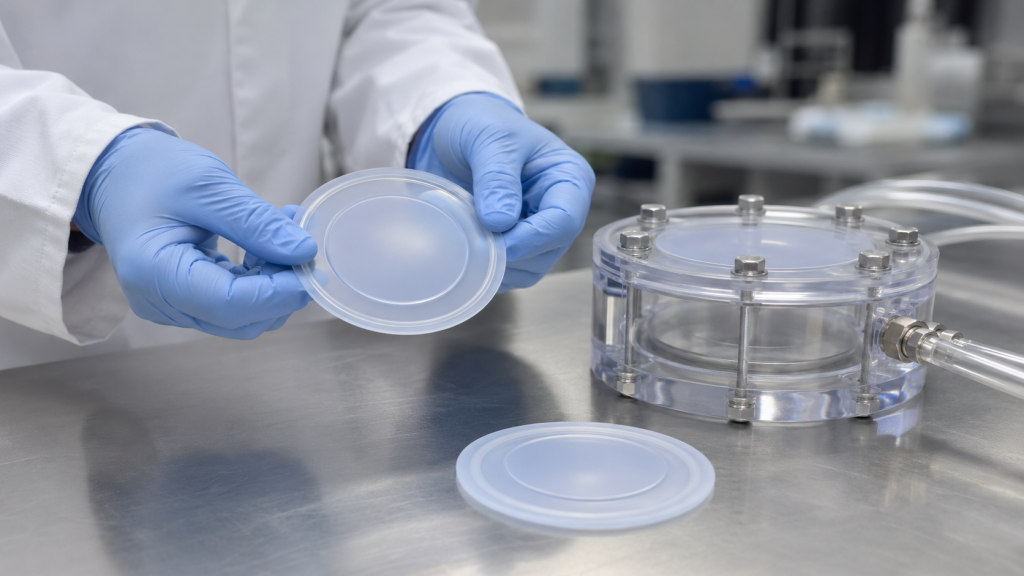
A silicone diaphragm is a thin, flexible membrane installed between two housing sections. Its outer edge is usually clamped or sealed while the central area moves in response to pressure.
Depending on the product, the diaphragm may perform one or several functions:
- Separate air from liquid
- Prevent contamination between chambers
- Transfer pressure
- Meter or pump fluid
- Actuate a valve
- Regulate pressure
- Detect pressure changes
- Provide a return force
- Protect an electronic sensor
- Compensate for volume changes
- Isolate aggressive media from mechanical components
Tra le applicazioni più comuni figurano:
- Medical pumps
- Ventilators
- Anesthesia equipment
- Respiratory devices
- Infusion equipment
- Laboratory analyzers
- Water valves
- Macchine da caffè
- Soap dispensers
- Pressure switches
- Automotive fluid systems
- Pneumatic controls
- Chemical dosing pumps
Trelleborg identifies silicone and other elastomeric diaphragm seals as solutions for low-pressure valves and respiratory equipment. It also notes that fabric reinforcement can be used for higher-pressure applications. Trelleborg Medical Diaphragm Seals
Pressure Range Is Not a Single Material Value
A silicone grade does not have one universal diaphragm pressure rating.
The maximum safe pressure depends on:
- Unsupported diameter
- Diaphragm thickness
- Diaphragm profile
- Modulo di elasticità del silicone
- Resistenza alla trazione
- Resistenza allo strappo
- Allungamento
- Clamping method
- Center support
- Operating stroke
- Temperatura
- Fluid compatibility
- Pressure waveform
- Cycle-life requirement
- Fattore di sicurezza
The same LSR material may survive a relatively high pressure in a small, supported diaphragm but fail at a much lower pressure when used in a larger unsupported membrane.
For this reason, pressure range should be specified at the component and assembly level—not only on the silicone material datasheet.
Define the Pressure Conditions Correctly
Several pressure values should be established before diaphragm design begins.
| Pressure term | Meaning |
|---|---|
| Minimum operating pressure | Lowest pressure at which the diaphragm must respond correctly |
| Nominal operating pressure | Normal working pressure during most of the product’s life |
| Maximum operating pressure | Highest continuous or repeated working pressure |
| Differential pressure | Pressure difference between the two sides of the diaphragm |
| Proof pressure | Temporary pressure the assembly must withstand without permanent damage |
| Burst pressure | Pressure at which rupture, pull-out or structural failure occurs |
| Vacuum condition | Negative pressure that may reverse the diaphragm or pull it against a housing surface |
| Pressure spike | Short transient pressure above normal operation |
| Pulsation range | Repeated minimum-to-maximum pressure during cycling |
A component designed for 100 kPa on one side and 90 kPa on the other experiences only 10 kPa differential pressure. A component exposed to 100 kPa on one side and vacuum on the other experiences a much larger differential.
The complete pressure history must therefore be considered.
Pressure Force and Effective Diameter
The approximate net force produced by a pressure differential can be estimated as:
Force = Differential pressure × Effective projected area
As effective diaphragm diameter increases, the area—and therefore the total pressure force—increases rapidly.
This means that a small increase in diameter can significantly increase:
- Membrane stress
- Center displacement
- Clamping load
- Required housing strength
- Risk of pull-out
- Burst-pressure demand
A larger diaphragm may provide greater sensitivity or displacement, but it generally requires more careful control of thickness and profile.
Main Silicone Diaphragm Configurations
Flat Diaphragm
A flat diaphragm is simple and economical. It can be suitable for limited movement and relatively small pressure differentials.
Potential limitations include:
- High strain during large displacement
- Strong sensitivity to clamping condition
- Stress concentration near the fixed edge
- Limited stroke before excessive stretching
Preformed or Dished Diaphragm
A shallow dome or dish provides additional material for movement.
Advantages can include:
- Greater stroke
- Reduced stretching
- Lower actuation force
- Better control of movement direction
The formed profile must remain stable during demolding, assembly and cycling.
Convoluted Diaphragm
One or more molded convolutions allow the diaphragm to flex through geometry rather than relying only on material stretching.
Potential benefits include:
- Longer stroke
- Lower spring rate
- Reduced membrane strain
- Improved cycle life
However, convolution depth, radii and wall thickness require precise control.
Rolling Diaphragm
A rolling diaphragm moves by rolling along a piston or housing surface.
It can provide:
- Long, controlled stroke
- Low friction
- Low hysteresis
- Good pressure response
The housing surface, alignment and diaphragm profile must be tightly controlled to prevent wrinkling or abrasion.
Fabric-Reinforced Diaphragm
A textile reinforcement layer increases dimensional stability and burst resistance.
Fabric-reinforced designs may be preferred for:
- Higher pressure
- Large diameters
- Low stretch
- Long stroke
- Precise pressure response
- Reduced ballooning
Trelleborg notes that higher pressure and burst resistance can be supported through synthetic-fabric reinforcement, while thinner homogeneous diaphragms can improve control sensitivity. Trelleborg Life Sciences Solutions
Insert-Molded Diaphragm
Metal or plastic inserts can be integrated into the diaphragm center or edge.
Insert molding may:
- Simplify assembly
- Improve force transfer
- Provide a connection to a valve stem
- Prevent center wear
- Improve positional repeatability
- Reduce secondary adhesive bonding
The insert should use chemical adhesion, mechanical locking or both.
How Thickness Affects Performance
Thickness is one of the most important diaphragm dimensions.
A small change can alter:
- Actuation force
- Pressure sensitivity
- Stroke
- Hysteresis
- Stress distribution
- Burst pressure
- Tempo di risposta
- Fatigue life
Thicker Diaphragms
Increasing thickness generally produces:
- Higher stiffness
- Lower displacement at the same pressure
- Higher required actuation force
- Improved resistance to pressure
- Better dimensional stability
- Lower risk of local tearing
Potential disadvantages include:
- Reduced sensitivity
- Shorter available stroke
- Higher stress at transitions
- Longer molding cure time
- Difficult filling in adjacent thin areas
Thinner Diaphragms
Reducing thickness generally produces:
- Lower actuation force
- Greater pressure sensitivity
- More displacement
- Faster movement
- Better response to small pressure differences
Potential disadvantages include:
- Higher strain
- Lower burst resistance
- Increased ballooning
- Greater sensitivity to thickness variation
- Higher risk of pinholes
- Greater risk of handling damage
In bending-dominated regions, stiffness can change approximately with the cube of thickness. However, a diaphragm often transitions into membrane stretching at larger deflections, so final behavior should be verified through simulation and physical testing.
Uniform Thickness vs. Designed Thickness Zones
Not every diaphragm should have one uniform thickness.
A functional design may include:
- A thicker clamping bead
- A thin flexible membrane
- Reinforced transition zones
- A thicker center pad
- Flexible convolutions
- A rigid insert interface
Thickness transitions should be gradual. Sudden changes can create local stress concentrations and become fatigue-initiation points.
The drawing should identify thickness requirements by functional zone rather than providing only one general thickness dimension.
Thickness-Control Challenges
Silicone diaphragms can be difficult to measure because the material is soft and flexible. Excessive probe force can compress the membrane and produce an incorrect result.
Possible measurement methods include:
- Low-force thickness gauge
- Non-contact optical measurement
- Laser scanning
- Optical comparator
- Controlled sectioning of qualification samples
- Coordinate measurement of supported parts
- Mold-cavity verification
- Part-weight monitoring as an indirect control
The inspection method should define:
- Measurement location
- Support fixture
- Contact force
- Probe diameter
- Conditioning time
- Temperatura
- Number of points
- Acceptance limits
Thickness variation near a convolution or radius may be more important than variation in a low-strain center area.
What Causes Thickness Variation?
Common manufacturing causes include:
- Mold-cavity mismatch
- Inserire movimento
- Uneven mold shut-off
- Inconsistent material loading
- Air entrapment
- Parting-line flash
- Tool deflection
- Uneven venting
- Riempimento incompleto
- Local cure variation
- Usura dovuta alla muffa
- Incorrect compression-molding charge position
For LSR injection molding, balanced gating, accurate cavity machining and stable process parameters are essential.
LSR Injection Molding vs. Compression Molding
Stampaggio a iniezione di LSR
Liquid silicone rubber injection molding is often selected for thin, complex or high-volume diaphragms.
Tra i vantaggi figurano:
- Repeatable material metering
- Produzione automatizzata
- Thin-section filling
- Complex profiles
- Cavità multiple
- Reduced manual handling
- Good suitability for cleanroom production
- Integration with plastic or metal inserts
LSR processing uses controlled injection rate, pressure, mold temperature and cure time. Component geometry and material chemistry both influence cycle time. SIMTEC LSR Injection Molding Guide
Stampaggio a compressione
Compression molding may be appropriate for:
- HCR silicone
- Lower production quantities
- Larger diaphragms
- Fabric-reinforced components
- Development tooling
- Selected thick or simple geometries
However, charge placement and compression flow can influence reinforcement position and thickness consistency.
Fabric-Reinforced Molding
Fabric must be accurately positioned before molding. Important controls include:
- Fabric orientation
- Tension
- Preforming
- Edge location
- Silicone penetration
- Wrinkle prevention
- Posizione di inserimento
- Cut-edge protection
A misaligned fabric layer can create asymmetric movement and inconsistent pressure response.
Silicone Material Selection
Durezza
A softer silicone may provide lower actuation force and greater movement. A harder material may improve dimensional stability and pressure resistance.
Hardness alone does not define diaphragm performance. Modulus at working strain is often more important than the Shore A value.
Tensile Strength and Elongation
The material must tolerate repeated stretching without permanent damage.
ASTM D412 provides methods for evaluating tensile strength and elongation of vulcanized rubber, but standard test-sheet values do not replace actual diaphragm cycling. ASTM D412
Resistenza allo strappo
Tear resistance is important near:
- Clamping edges
- Holes
- Insert interfaces
- Gate-removal areas
- Flash-trimmed edges
- Sharp housing features
A very small notch can become a fatigue crack after thousands or millions of cycles.
Compression Set
The sealing bead may remain compressed for the entire product life. Excessive compression set can reduce clamping force and cause leakage.
ASTM D395 evaluates the ability of rubber to retain elastic properties after prolonged compressive stress, although dynamic diaphragm life still requires application-specific testing. ASTM D395
Stress Relaxation
Even if the material does not show severe permanent deformation, clamping force may decrease over time. This can affect perimeter sealing and diaphragm retention.
Fluid Compatibility
The silicone must be tested with the actual operating media, including:
- Acqua
- Vapore
- Saline
- Medication
- Detergent
- Petrolio
- Fuel
- Prodotti chimici per la pulizia
- Food ingredients
- Disinfettanti
- Process gases
Exposure can cause swelling, softening, hardening, extraction or loss of mechanical strength.
Temperatura
Temperature changes both the silicone properties and the fluid behavior.
The design should consider:
- Minimum operating temperature
- Maximum continuous temperature
- Short temperature peaks
- Sterilization temperature
- Storage temperature
- Cicli termici
Regulatory Requirements
Depending on the application, requirements may include:
- FDA food-contact compliance
- Classe VI dell'USP
- ISO 10993 evaluation
- RoHS
- REACH
- Customer-specific extractables limits
- Medical-device traceability
- Produzione in camera bianca
The regulatory status of the raw material does not automatically certify the finished diaphragm for every application.
Diaphragm DFM Guidelines
Use Smooth Radii
Sharp internal corners concentrate stress. Use smooth radii where the flexible membrane joins:
- Clamping beads
- Center pads
- Convolutions
- Inserts
- Sezioni spesse
Keep the Parting Line Away from Critical Flex Zones
Parting-line mismatch or flash can create a notch that grows during repeated movement.
Whenever possible, place the parting line away from the highest-strain region.
Control Gate Position
The gate should not create a weak point in the working membrane.
Avoid gate marks in areas exposed to:
- Repeated bending
- High stretch
- Sealing contact
- Fluid flow
- Cosmetic inspection
Provide Effective Venting
Thin diaphragms can trap air at the end of fill. Poor venting may cause:
- Short shots
- Fori minuscoli
- Burned areas
- Weak knit lines
- Thickness variation
Because LSR flows easily, vents must also be designed to limit flash.
Design the Clamping Bead Carefully
The perimeter bead may provide:
- Sealing
- Positioning
- Retention
- Compression control
The housing should compress the bead sufficiently to seal without pinching the membrane or forcing it into the moving zone.
Avoid Excessive Assembly Stretch
A diaphragm should not be pulled significantly out of shape during installation unless controlled pre-tension is part of the design.
Uncontrolled stretch changes:
- Effective thickness
- Stroke
- Pressure response
- Fatigue life
- Sealing force
Housing Design and Assembly
The diaphragm and housing must be developed as one system.
Important housing factors include:
- Clamp width
- Clamp gap
- Finitura superficiale
- Edge radii
- Alignment
- Available stroke space
- Vent paths
- Distanza tra gli elementi di fissaggio
- Flatness
- Assembly torque
- Protection against overcompression
Uneven fastener torque can distort the sealing bead and change diaphragm movement.
If the diaphragm can contact a housing wall during operation, the contact surface should be smooth and free of sharp edges.
Pressure-Displacement Testing
A pressure-displacement test measures how far the diaphragm moves at different pressure levels.
The test can evaluate:
- Sensitivity
- Spring rate
- Hysteresis
- Maximum stroke
- Return position
- Permanent set
- Cavity-to-cavity variation
A typical test records diaphragm displacement while pressure is increased and then decreased.
The loading and unloading curves may not be identical because silicone is viscoelastic. The difference between them is part of the diaphragm’s hysteresis.
Proof-Pressure Testing
Proof pressure confirms that the diaphragm can withstand a temporary pressure above normal operation without:
- Leakage
- Rupture
- Pull-out
- Deformazione permanente
- Insert separation
- Loss of functional response
After proof testing, the component should be returned to normal conditions and tested again for displacement, leakage and appearance.
Burst-Pressure Testing
Burst testing determines the pressure at which structural failure occurs.
Possible failure modes include:
- Membrane rupture
- Tearing at the clamped edge
- Insert pull-out
- Bead extrusion
- Housing separation
- Fabric delamination
- Leakage before rupture
Burst pressure should be tested using a protected fixture and controlled pressure ramp.
A production specification may require a minimum burst value rather than testing every part to destruction.
Leak Testing
Leakage can occur through:
- The silicone membrane
- A pinhole
- The perimeter seal
- An insert interface
- A molded knit line
- Housing deformation
Common leak-test methods include:
- Pressure decay
- Vacuum decay
- Bubble testing
- Direct flow measurement
- Tracer-gas testing
- Liquid hold testing
The method should define:
- Test media
- Pressione
- Tempo di stabilizzazione
- Durata del test
- Temperatura
- Allowable leakage
- Fixture volume
- Pass/fail calculation
Cycle-Life Testing
Cycle-life testing is essential because many diaphragm failures develop gradually.
A diaphragm may pass initial proof-pressure and leakage tests but fail after repeated flexing.
Define a Realistic Pressure Waveform
The cycle should reproduce the actual application as closely as possible.
Possible waveforms include:
- Minimum-to-maximum pressure
- Positive pressure to vacuum
- Pulsed pressure
- Constant displacement
- Mechanical actuation
- Pressure with fluid flow
- Pressure dwell followed by rapid release
The test should not automatically use a simple maximum-to-zero cycle if the real product behaves differently.
Define Cycle Frequency
Running a test too quickly can generate heat and create a failure mechanism that would not occur in normal service.
Cycle frequency should consider:
- Actual operating speed
- Silicone heat buildup
- Fluid heating
- Valve response time
- Test-fixture limitations
Accelerated testing is useful only when the acceleration method does not change the fundamental failure mode.
Define the Mission Profile
A complete cycle requirement should state:
- Total number of cycles
- Intervallo di pressione
- Displacement or stroke
- Frequency
- Duty cycle
- Tempo di permanenza
- Temperatura
- Test media
- Assembly condition
- Inspection intervals
Measure Performance During Cycling
Do not wait until the final cycle to inspect the diaphragm.
Periodic checks may include:
- Leakage
- Pressure-displacement response
- Return position
- Visual cracking
- Deformazione permanente
- Inserire movimento
- Thickness change
- Actuation force
Define the Failure Criteria
Possible failure criteria include:
- Visible crack
- Pin-hole leakage
- Excessive change in displacement
- Reduced pressure response
- Deformazione permanente
- Insert separation
- Perimeter leakage
- Failure to return
- Burst-pressure reduction
Factors That Reduce Cycle Life
Excessive Strain
Large displacement in a flat diaphragm can produce high membrane strain. A convolution or preformed shape may reduce strain.
Sharp Transitions
Small radii and abrupt thickness changes create localized stress.
Surface Defects
Flash, trimming damage, scratches and contamination can initiate cracks.
Incorrect Clamping
Overcompression or edge pinching can damage the flexible transition.
Material Aging
Heat, chemicals, sterilization and UV exposure may change silicone properties.
Abrasion
Contact with a rough housing surface can gradually wear through the diaphragm.
Insert Stress
A rigid center insert can create high strain around its edge if the transition is not properly designed.
Pressure Spikes
Short pressure events may exceed the intended stress level even when average operating pressure is low.
Simulation and Finite Element Analysis
Finite element analysis can help compare diaphragm designs before tooling.
Useful outputs include:
- Stress distribution
- Strain concentration
- Displacement
- Contact with the housing
- Clamping effects
- Caricamento in corso
- Pressure response
The material model should represent the hyperelastic behavior of the selected silicone.
Possible models include:
- Mooney-Rivlin
- Ogden
- Neo-Hookean
- Yeoh
Accurate simulation requires material test data over the expected strain range. A generic elastic modulus is usually insufficient for large diaphragm deformation.
Simulation should guide prototype design, but physical testing remains essential.
Typical Validation Sequence
Stage 1: Material Screening
Compare candidate silicone grades for:
- Durezza
- Modulus
- Resistenza alla trazione
- Allungamento
- Resistenza allo strappo
- Deformazione residua da compressione
- Fluid compatibility
- Regulatory status
Stage 2: Prototype Geometry
Evaluate controlled variations in:
- Spessore della membrana
- Effective diameter
- Convolution depth
- Center-pad size
- Clamping bead
- Insert geometry
Stage 3: Functional Testing
Misura:
- Pressure-displacement response
- Hysteresis
- Leakage
- Proof pressure
- Burst pressure
- Actuation force
Stage 4: Environmental Conditioning
Retest after:
- Heat aging
- Fluid immersion
- Cicli termici
- Sterilizzazione
- Storage aging
- Humidity exposure
Stage 5: Cycle-Life Testing
Run the production-intent diaphragm inside the production-intent housing.
Fase 6: Produzione pilota
Conferma:
- Thickness consistency
- Cavity-to-cavity performance
- Posizione di inserimento
- Assembly repeatability
- Inspection capability
- Test-fixture stability
- Tracciabilità
Modalità di guasto più comuni e azioni correttive
| Problem | Possibile causa | Azioni correttive |
| Diaphragm ruptures at center | Membrane too thin or pressure too high | Increase thickness or add support |
| Tearing occurs at outer edge | Sharp clamping edge or excessive strain | Increase radius and revise clamp design |
| Pressure response is too low | Membrane too thick or material too hard | Reduce stiffness or change profile |
| Diaphragm moves too far | Membrane too flexible or effective area too large | Increase thickness or add a travel stop |
| Perimeter leakage | Insufficient bead compression or uneven housing | Revise bead, clamp gap and assembly torque |
| Cycle life is inconsistent | Thickness or surface-defect variation | Improve tooling and cavity-level inspection |
| Diaphragm does not return | Material set, excessive stretch or vacuum lock | Review material, profile and venting |
| Insert separates | Poor bonding or high edge stress | Add mechanical locking and improve transition |
| Fabric wrinkles | Poor preforming or location | Improve fabric fixture and molding process |
| Cracks form after sterilization | Material degradation or residual stress | Validate the material and post-cure process |
| Diaphragm sticks to housing | Surface contact or fluid residue | Increase clearance or modify surface finish |
Production Quality Control
A diaphragm production-control plan may include:
- Raw-material lot traceability
- LSR mixing-ratio monitoring
- Mold-temperature records
- Cure-time control
- Cavity identification
- Part weight
- Critical thickness measurements
- Membrane-profile inspection
- Ispezione rapida
- Insert-position inspection
- Perimeter-bead dimensions
- Pressure-displacement sampling
- Prove di tenuta
- Proof-pressure sampling
- Periodic cycle-life verification
- Cleanliness and packaging inspection
For multi-cavity tools, thickness and functional data should be reviewed by cavity.
RFQ Checklist for Custom Silicone Diaphragms
Provide the following information for an accurate quotation and DFM review:
- Disegno 2D
- File CAD 3D
- Diaphragm type
- Effective diameter
- Available installation space
- Required stroke
- Minimum operating pressure
- Nominal operating pressure
- Maximum operating pressure
- Vacuum condition
- Proof pressure
- Burst-pressure requirement
- Pressure waveform
- Cycle-life target
- Cycle frequency
- Fluid or gas type
- Temperatura di esercizio
- Metodo di sterilizzazione o pulizia
- Silicone hardness preference
- Requisiti normativi
- Reinforcement requirements
- Insert material
- Required leakage rate
- Thickness tolerance
- Housing drawing
- Metodo di montaggio
- Quantità del prototipo
- Domanda annuale
- Inspection-report requirements
- Requisiti relativi all'imballaggio e alla pulizia
Avoid providing only a nominal pressure value. The manufacturer also needs the effective area, maximum differential pressure, stroke, temperature, media and cycle requirement.
Domande frequenti
What pressure can a silicone diaphragm withstand?
There is no universal pressure rating. Pressure capability depends on effective diameter, thickness, profile, material, clamping method, temperature and required cycle life.
Does increasing thickness always improve diaphragm life?
Not always. Greater thickness can improve pressure resistance but may increase stiffness and stress at transition areas. The correct thickness balances movement, strain and pressure.
Is LSR suitable for very thin diaphragms?
Yes. LSR can fill thin and complex geometries, but tooling precision, venting, flash control and thickness inspection become increasingly important.
When is fabric reinforcement required?
Fabric reinforcement may be considered for larger diameters, higher pressure, longer strokes, reduced ballooning or more stable pressure response.
Can a diaphragm be molded with a metal insert?
Yes. Metal or plastic inserts can be overmolded into the center or perimeter. Bonding and mechanical locking should be validated through pull, leak and cycle testing.
What is the difference between proof pressure and burst pressure?
Proof pressure confirms that the part survives a specified overload without damage. Burst pressure identifies the pressure at which structural failure occurs.
How many cycles should a diaphragm be tested?
The requirement depends on the product mission profile. The test should represent expected service life plus an appropriate validation margin.
Can cycle-life testing be accelerated?
Yes, but excessive test frequency, temperature or pressure can introduce unrealistic failure modes. The acceleration method should be technically justified.
Why must the diaphragm be tested inside the housing?
The housing controls clamping, compression, clearance and available stroke. A loose diaphragm may perform differently from the assembled component.
How is thickness measured on a soft diaphragm?
Low-force contact gauges or non-contact optical methods are preferred. The measurement locations, support fixture and contact force must be defined.
Conclusione
Custom silicone diaphragm performance depends on more than selecting a silicone hardness and nominal thickness.
Pressure rating, displacement, sealing and cycle life are controlled by the complete system:
- Effective diameter
- Membrane profile
- Thickness distribution
- Silicone material
- Edge radii
- Clamping bead
- Housing geometry
- Operating pressure
- Temperatura
- Media exposure
- Cycle waveform
The most reliable development process combines DFM, material testing, nonlinear simulation, prototype molding, pressure-displacement measurement, proof and burst testing, environmental conditioning and full cycle-life validation.
For a custom silicone diaphragm project, provide the operating pressure range, diaphragm diameter, required stroke, media, temperature, housing design and cycle-life target. These details allow the manufacturer to recommend the appropriate LSR grade, thickness profile, reinforcement method, tooling process and validation plan.
 English
  Japanese
  Korean
  German
  French
  Italian
  Spanish
  Dutch
Dutch  Chinese
  Portuguese
  Polish
  Czech
Czech  Hungarian
  Swedish
  Finnish
  Vietnamese
  Thai
Thai  Turkish
  Arabic
  Russian