
Silicone overmolding is widely used to combine soft silicone with rigid plastic or metal components.
This manufacturing method can improve sealing, grip, waterproofing, shock absorption, insulation, and product integration.
Parmi les applications courantes, on peut citer :
- Dispositifs médicaux
- Électronique grand public
- Composants automobiles
- Connecteurs étanches
- Handheld tools
- Industrial equipment
- Baby care products
- Composants d'étanchéité
However, silicone overmolding is more complex than standard silicone molding.
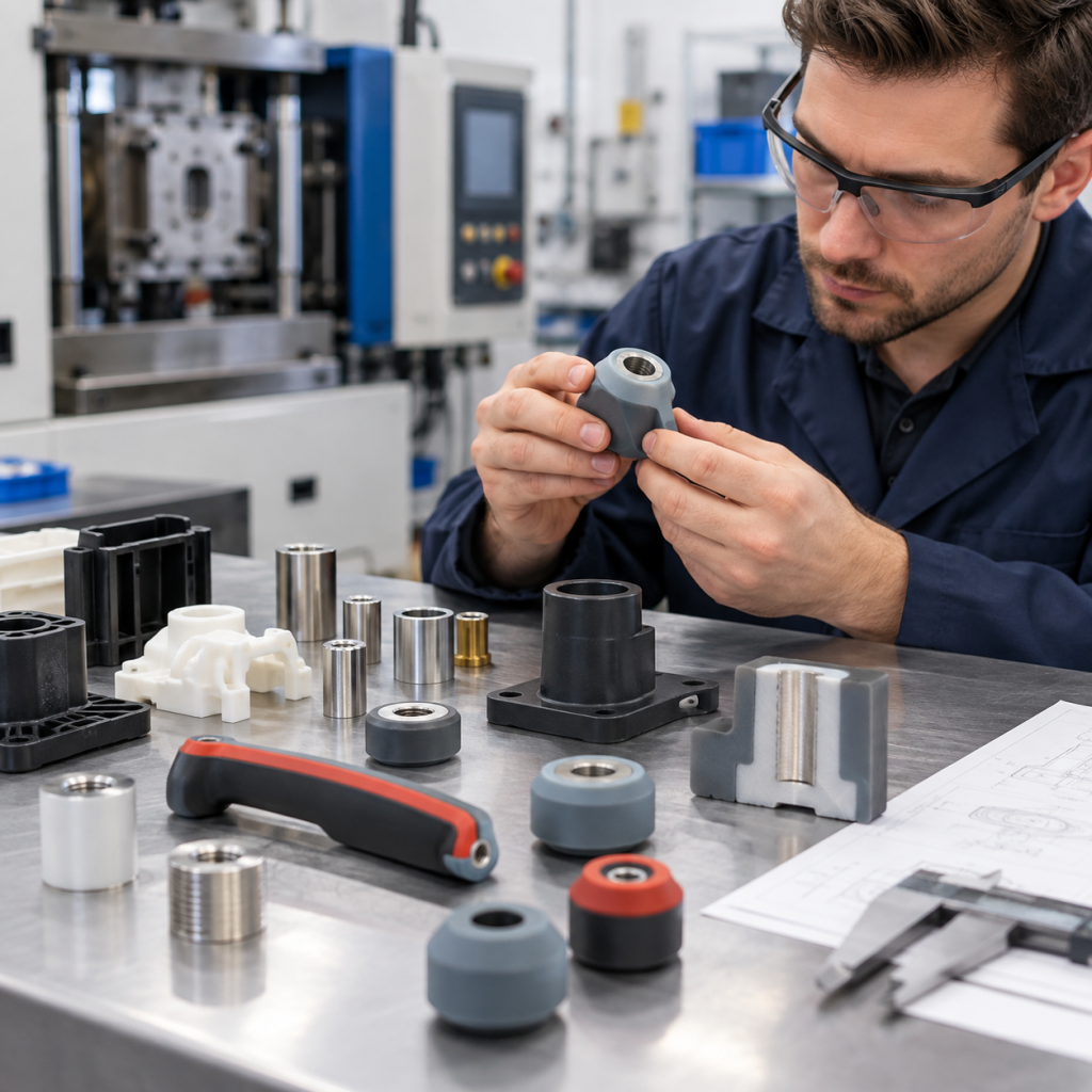
The success of the project depends on material compatibility, insert design, mold structure, surface treatment, bonding method, dimensional tolerance, and process control.
Poor design can lead to common failures such as:
- Délamination
- Liaison faible
- Flash
- Bulles d'air
- Mouvement d'insertion
- Plastic deformation
- Remplissage incomplet
- Déchirure du silicone
- Fuite
This guide explains the key design principles for custom silicone overmolding projects.
1. Qu'est-ce que le surmoulage au silicone ?
Silicone overmolding is a process where silicone rubber is molded directly onto a rigid substrate.
The substrate may be:
- Plastique
- Acier inoxydable
- Aluminium
- Brass
- Other metals
- Pre-molded components
The rigid insert is placed into the mold first.
Silicone is then molded around or onto the insert.
Depending on the project, the silicone may bond chemically to the substrate or be locked mechanically into the structure.
The result is a single integrated component.
2. Why Use Silicone Overmolding?
Silicone overmolding can replace separate assembly steps.
Instead of manufacturing a rigid component and silicone part separately and assembling them later, both materials can be integrated during molding.
Typical benefits include:
- Moins de composants
- Reduced assembly time
- Étanchéité améliorée
- Better sealing consistency
- Improved grip
- Better vibration absorption
- Reduced risk of loose gaskets
- Cleaner product appearance
- Improved product durability
For high-volume products, integrated overmolding can also reduce long-term assembly cost.
3. Common Silicone Overmolding Materials
Silicone can be overmolded onto many substrate materials, but not every combination provides reliable bonding.
Parmi les matériaux couramment utilisés comme substrat, on peut citer :
Plastiques
- PC
- PA
- PBT
- PPSU
- PEI
- ABS
- Selected engineering plastics
Métaux
- Acier inoxydable
- Aluminium
- Brass
- Steel
- Copper alloys
The correct process depends on the substrate material, surface condition, molding temperature, and required bond strength.
4. LSR Is Commonly Used for Overmolding
Liquid Silicone Rubber, or LSR, is widely used for silicone overmolding.
Its low viscosity allows the material to flow around complex inserts and into small features.
LSR is especially suitable for:
- Precision components
- Thin silicone layers
- Complex sealing structures
- Production à grande échelle
- Automated insert molding
Parmi les applications courantes, on peut citer :
- Medical device handles
- Electronic housings
- Connecteurs étanches
- Automotive seals
- Plastic valve components
- Metal-silicone assemblies
HCR silicone can also be used for overmolding, but LSR is often preferred for precision and automated applications.
5. Chemical Bonding vs Mechanical Bonding
Silicone can be attached to the substrate in two main ways.
Chemical Bonding
Chemical bonding creates adhesion between the silicone and substrate surface.
This may involve:
- LSR auto-adhésif
- Introduction
- Activation de surface
- Traitement au plasma
- Special substrate preparation
Chemical bonding can provide a clean integrated structure.
However, it is sensitive to:
- Contamination de surface
- Agents de démoulage
- Nuance de matériau
- Énergie de surface
- Processing temperature
Mechanical Bonding
Mechanical bonding does not rely only on chemical adhesion.
Instead, the insert contains physical structures that lock the silicone in place.
En voici quelques exemples :
- Trous
- Contre-dépouilles
- Rainures
- Machines à sous
- Côtes
- Dovetail structures
Mechanical locking is often used when chemical adhesion is uncertain.
In many projects, both chemical and mechanical bonding are combined.
6. Design Mechanical Locking Features
Mechanical retention can greatly improve overmolding reliability.
Useful features include:
- Trous traversants
- Side holes
- Recesses
- Rainures
- Nervures de retenue
- Anchor points
Silicone flows into these features during molding.
After curing, the silicone becomes physically locked to the insert.
This is particularly useful for:
- Inserts métalliques
- Low-adhesion plastics
- High-load components
- Long-term durability applications
7. Avoid Extremely Thin Silicone Layers
Very thin silicone layers are difficult to mold consistently.
Les problèmes peuvent notamment inclure :
- Remplissage incomplet
- Déchirure
- Épaisseur irrégulière
- Mauvaise adhérence
- Air trapping
The minimum practical thickness depends on:
- LSR viscosity
- Flow length
- Product geometry
- Injection location
- Température du moule
Thin sections should be reviewed during DFM.
8. Maintain Uniform Wall Thickness
Large changes in silicone thickness can create uneven filling and curing.
Whenever possible, avoid sudden transitions between thick and thin sections.
Smooth transitions can improve:
- Flux de matières
- Qualité de surface
- Liaison
- Stabilité dimensionnelle
Uniform wall thickness also helps reduce internal stress.
9. Insert Positioning Is Critical
The insert must remain stable during silicone injection.
If the insert moves, the final product may have:
- Uneven silicone thickness
- Incorrect dimensions
- Exposed substrate
- Misalignment
- Poor sealing
The mold should support the insert with suitable locating features.
Voici quelques solutions possibles :
- Pins
- Rainures
- Fixtures
- Clamping surfaces
- Dedicated insert nests
Insert positioning becomes especially important in high-pressure molding.
10. Consider Injection Pressure
LSR injection can apply pressure to the insert.
Thin plastic parts may deform.
Lightweight inserts may move.
The designer should consider:
- Insert stiffness
- Épaisseur de la paroi
- Support points
- Gate location
- Injection speed
Weak inserts may require additional support in the mold.
11. Plastic Deformation During Overmolding
Some plastics can deform under molding temperature or pressure.
Parmi les problèmes potentiels, on peut citer :
- Warping
- Shrinkage
- Dommages superficiels
- Dimensional changes
The plastic must be compatible with the overmolding process.
High-temperature engineering plastics are generally more suitable than low-temperature plastics.
The manufacturer should review the thermal characteristics before tooling.
12. Surface Preparation for Metal Inserts
Metal surfaces may require cleaning or treatment before overmolding.
Common preparation steps include:
- Dégraissage
- Ultrasonic cleaning
- Sandblasting
- Traitement au plasma
- Application de l'apprêt
Oil, dust, oxidation, or machining residue can reduce adhesion.
Good surface preparation is particularly important for chemical bonding.
13. Surface Preparation for Plastic Inserts
Plastic substrates can also require treatment.
Depending on the material, possible treatments include:
- Plasma activation
- Traitement contre le coronavirus
- Introduction
- Controlled cleaning
The selected method depends on the plastic type and bonding system.
14. Self-Bonding LSR
Self-bonding LSR is formulated to bond directly to certain substrates.
It can reduce the need for separate primer application.
This can improve:
- Automatisation
- Production consistency
- Propreté
- Durée du cycle
However, self-bonding LSR does not bond equally well to every plastic or metal.
Testing should be completed before mass production.
15. Gate Location
Gate design influences material flow.
Poor gate placement can cause:
- Lignes de soudure
- Pièges à air
- Remplissage incomplet
- Pression inégale
- Insert displacement
The gate should allow silicone to flow evenly around the insert.
For complex parts, mold flow analysis may be useful.
16. Venting
Air trapped inside the cavity must escape during injection.
Poor venting can lead to:
- Bulles d'air
- Traces de brûlure
- Remplissage incomplet
- Défauts de surface
Vents should be placed in areas where air is likely to accumulate.
17. Parting Line Design
Parting line location is especially important for overmolded sealing components.
A poor parting line can create flash on functional surfaces.
Critical areas should avoid unnecessary flash.
This includes:
- Sealing surfaces
- Cosmetic surfaces
- Assembly surfaces
- Contact areas
The parting line should be defined during mold design.
18. Flash Control
Silicone can flow into extremely small gaps.
This means poor mold fit can cause flash.
Flash is especially problematic around:
- Inserts métalliques
- Inserts en plastique
- Sealing interfaces
- Thin edges
Precision mold manufacturing and insert control are essential.
The insert itself must also maintain consistent dimensions.
19. Silicone Leakage Around the Insert
If there is too much clearance around the insert, silicone may flow into unwanted areas.
This can create:
- Excess flash
- Contamination
- Assembly problems
- Cosmetic defects
The mold must provide a reliable shutoff surface around the insert.
20. Shutoff Surface Design
A shutoff surface prevents silicone from flowing past a controlled boundary.
The shutoff must be strong enough to resist injection pressure.
Poor shutoff design can cause severe flashing.
Parmi les facteurs importants, on peut citer :
- Planéité de la surface
- Insert tolerance
- Mold tolerance
- Force de serrage
- Surface contact area
21. Bonding Area
A very small bonding area may not provide enough adhesion.
Increasing the bonding area can improve mechanical strength.
Possible approaches include:
- Wider silicone contact surfaces
- Rainures
- Trous
- Côtes
- Wrap-around geometry
The design should distribute load across the bonded area.
22. Avoid Peel Loading
Silicone-to-substrate bonds usually perform better under shear or compression than direct peeling.
If possible, avoid designs where the silicone can be peeled away from the substrate.
Better structures protect the bond edge.
Mechanical locking can also reduce peel stress.
23. Common Failure: Delamination
Delamination is one of the most common overmolding failures.
The silicone separates from the plastic or metal substrate.
Possible causes include:
- Matériaux incompatibles
- Contamination de surface
- Incorrect primer
- Mauvais traitement de surface
- Insufficient curing
- Low bonding area
- Excessive peel stress
The solution may require both material and design changes.
24. Common Failure: Air Bubbles
Air bubbles may appear at the interface or inside the silicone.
Possible causes include:
- Poor venting
- Trapped moisture
- Inserts contaminés
- Poor flow path
- Incorrect injection settings
The mold and process must allow trapped air to escape.
25. Common Failure: Incomplete Filling
Incomplete filling occurs when silicone does not completely fill the cavity.
Possible causes include:
- Thin walls
- Long flow distance
- Poor gate location
- Low injection pressure
- Low mold temperature
- Air emprisonné
Design optimization can often solve this problem.
26. Common Failure: Insert Movement
The insert may shift during molding.
Possible causes include:
- Insufficient locating features
- High injection pressure
- Poor fixture design
- Insert dimensional variation
Better insert support and mold positioning can improve consistency.
27. Common Failure: Flash
Flash may form around the insert or parting line.
Possible causes include:
- Insert tolerance variation
- Usure des moules
- Poor shutoff
- Excessive pressure
- Poor mold alignment
Tight tooling control is essential for precision overmolding.
28. Common Failure: Silicone Tearing
Silicone may tear during demolding or use.
Possible causes include:
- Thin edges
- Angles vifs
- Poor demolding direction
- High local stress
- Insufficient material thickness
Rounded transitions and adequate wall thickness improve durability.
29. Common Failure: Plastic Warpage
Plastic inserts may deform during molding.
Possible causes include:
- Excessive mold temperature
- Thin plastic walls
- High injection pressure
- Poor support
Material selection and mold support should be reviewed.
30. Overmolding for Waterproof Electronics
Silicone overmolding is commonly used for electronic sealing.
Parmi les applications, on peut citer :
- Waterproof buttons
- Joints d'étanchéité pour connecteurs
- Cable entries
- Protective housings
- Caches pour capteurs
Integrated silicone sealing can reduce the risk of missing or incorrectly installed gaskets.
31. Overmolding for Medical Devices
Medical silicone overmolding may be used for:
- Poignées
- Seals
- Vannes
- Connecteurs
- Flexible interfaces
Medical projects may require additional consideration of:
- Biocompatibilité
- Traçabilité des matériaux
- Propreté
- Validation
- Compatibilité avec la stérilisation
32. Overmolding for Automotive Components
Automotive overmolding applications include:
- Connecteurs étanches
- Sensor seals
- Cable components
- Vibration-resistant parts
- Electronic housings
These components may need to withstand:
- Chaleur
- Cold
- Vibration
- Oil exposure
- Humidité
- Cycles thermiques
33. Tolerance Stack-Up
Overmolded parts combine tolerances from multiple components.
The final dimension may depend on:
- Insert tolerance
- Mold tolerance
- Silicone shrinkage
- Positioning tolerance
Tolerance stack-up should be reviewed before tooling.
34. Prototype Before Mass Production
For complex overmolding projects, prototype testing is strongly recommended.
Prototypes can help evaluate:
- Résistance d'adhérence
- Qualité de surface
- Stabilité dimensionnelle
- Flash
- Assemblage
- Performances d'étanchéité
This can reduce expensive tooling changes later.
35. Bond Strength Testing
Bond strength should be verified when adhesion is critical.
Possible tests include:
- Peel testing
- Pull testing
- Shear testing
The test method should match the real product load.
36. Environmental Testing
For demanding applications, overmolded components may also require:
- Cycles thermiques
- Humidity testing
- Essais de vieillissement
- Essais de vibration
- Water immersion
- Exposition à des substances chimiques
These tests help evaluate long-term bond reliability.
37. What Information Should You Send for a Silicone Overmolding Quote?
For an accurate quotation, provide:
- Dessin en 2D
- Fichier CAO 3D
- Insert material
- Exigences relatives au silicone
- Dureté du silicone
- Bonding requirement
- Finition de surface
- Dimensions critiques
- Estimated annual volume
- Quantité de la commande initiale
- Candidature
- Conditions environnementales
If the insert already exists, physical samples can also help during engineering review.
Conclusion
Silicone overmolding can provide excellent sealing, grip, protection, and product integration.
However, successful overmolding requires careful coordination between material selection, insert design, bonding method, mold structure, and process control.
Parmi les facteurs de conception les plus importants, on peut citer :
- Substrate compatibility
- Verrouillage mécanique
- Bonding area
- Positionnement de l'insert
- Épaisseur de la paroi
- Conception des portails
- Évacuation
- Shutoff surfaces
- Contrôle du flash
- Tolerance stack-up
A DFM review before tooling can identify many potential problems and reduce the risk of delamination, flash, air bubbles, insert movement, and poor sealing.
Fuhongying provides custom silicone overmolding and LSR insert molding services for plastic and metal components.
We support OEM and ODM projects for medical devices, consumer electronics, automotive parts, sealing components, baby care products, and industrial applications.
Send us your 2D drawing, 3D file, insert material, application, and estimated quantity for a DFM review and quotation.
FAQ
Can silicone bond directly to plastic?
Yes, but bonding depends on the plastic type, silicone formulation, surface preparation, and molding conditions. Some projects use self-bonding LSR, while others require primer or mechanical locking.
Can silicone be overmolded onto metal?
Yes. Silicone can be overmolded onto stainless steel, aluminum, brass, and other metals. Surface cleaning and mechanical retention are often important.
What causes silicone overmolding to delaminate?
Common causes include incompatible materials, surface contamination, poor surface treatment, insufficient bonding area, incorrect curing conditions, and excessive peel stress.
Is LSR better than HCR for overmolding?
LSR is often preferred for precision, complex, thin-wall, and high-volume overmolding because it can be highly automated. HCR can also be used depending on product design and volume.
How can flash be reduced in silicone overmolding?
Flash can be reduced through precision mold machining, stable insert dimensions, good shutoff design, proper clamping, and controlled injection parameters.
Should mechanical locking be added if chemical bonding is used?
In many applications, yes. Combining chemical adhesion with mechanical locking can improve long-term reliability, especially in demanding environments.
 English
  Japanese
  Korean
  German
  French
  Italian
  Spanish
  Dutch
Dutch  Chinese
  Portuguese
  Polish
  Czech
Czech  Hungarian
  Swedish
  Finnish
  Vietnamese
  Thai
Thai  Turkish
  Arabic
  Russian