
模製矽膠元件通常僅是較大型組件中的一部分。它可能需要與塑膠外殼、金屬嵌件、電纜、感測器、閥門、管路或其他矽膠零件連接。該組件必須保持穩固,同時須符合密封性、柔韌性、潔淨度及長期耐用性的要求。.
若選用不當的接合方式,可能會導致使用過程中出現黏合劑剝離、矽膠撕裂、嵌件移位或滲漏等問題。因此,可靠的设计應從一開始就綜合考量接合處的幾何形狀、材料組合、受力方向、製造製程及檢驗方法。.
本指南比較了矽膠黏合、機械鎖定及混合組裝方法,並說明如何運用壓力衰減、真空衰減、質量流量及示蹤氣體測試來驗證密封性能。.
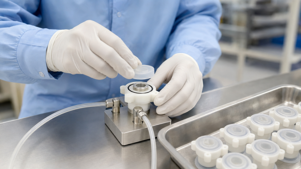
為何矽膠零件難以組裝
矽膠具有柔韌性、耐高溫性及良好的密封性能,但正是這些特性,也為組裝過程帶來了挑戰。.
常見的困難包括:
- 表面能較低,導致附著力受限
- 在定位過程中會變形的柔性零件
- 密封區域周圍的可變壓縮
- 脫模殘留物或污染物
- 矽膠與剛性基材之間的熱膨脹係數不同
- 暴露接合邊緣處的高剝離應力
- 包覆成型過程中嵌件的位移
- 薄矽膠截面的氣體滲透性
- 難以區分夾具洩漏與產品洩漏
首要的設計決策在於,該接合處是否需要化學黏著、機械固定,抑或兩者兼具。.
主要的矽膠組裝方法
| 方法 | 典型應用 | 主要優勢 | 主要限制 |
|---|---|---|---|
| 矽膠黏合 | 矽膠對矽膠、金屬或塑膠組裝 | 柔性連續接頭 | 需進行表面處理及固化 |
| 底漆輔助黏合 | 難以處理的塑膠、金屬或玻璃基材 | 提升界面黏著力 | 額外的受控製程步驟 |
| 自黏合液態矽膠包覆成型 | 大批量生產的矽膠轉塑膠或金屬零組件 | 自動化整合組裝 | 必須驗證材料相容性 |
| 機械式互鎖裝置 | 墊片、外殼、嵌件及線纜組件 | 並非完全仰賴化學作用 | 需要額外的幾何結構與工裝 |
| 壓縮擷取 | 密封件、隔膜及可更換墊片 | 簡單且實用 | 壓縮程度必須保持在可控範圍內 |
| 化學-機械混合接頭 | 關鍵密封與結構組件 | 冗餘保留 | 更多設計與驗證工作 |
| 緊固件、夾具或壓接 | 管件、外殼及可現場維修的組件 | 易於檢查或拆卸 | 局部矽膠損傷的風險 |
1. 矽膠黏合
黏合工藝是用於將模具成型後分別製造的組件進行接合。視組裝需求而定,所使用的黏合劑可能是單組分 RTV 矽膠、雙組分矽膠黏合劑,或是其他相容的柔性黏合劑系統。.
矽膠與矽膠之間的黏合
當兩個組件均為矽膠時,常會使用矽膠黏合劑。若選用適當的黏合劑,即可形成具有彈性的接合處,使其能隨模製組件一同移動。.
常見的應用包括:
- 將矽膠管與模製連接器接合
- 閥門組件的黏接
- 將矽膠密封圈安裝於柔性基體上
- 修復或封閉模製矽膠組件
- 將兩種硬度不同的矽膠進行黏合
表面必須保持清潔,且不得殘留油漬、灰塵、未固化材料及脫模劑殘留物。部分已固化的矽膠表面可能還需要進行等離子、電暈或底漆處理。.
矽膠與塑膠的黏合
將矽膠與熱塑性塑料進行黏合可能較為困難,因為黏合效果取決於具體的樹脂種類、添加劑、玻璃纖維含量以及表面狀況。.
重要的變數包括:
- 確切的聚合物等級
- 水分含量
- 脫模添加劑
- 表面質地
- 耐熱性
- 黏合劑固化條件
- 使用過程中的化學物質暴露
針對某種聚碳酸酯或尼龍等級所開發的黏合劑,不應自動假設其適用於其他等級。.
矽膠與金屬的接合
金屬嵌件通常應無切削油、氧化物、灰塵及指紋。可能需要進行脫脂、受控表面粗糙化處理、等離子處理或塗佈底漆。.
合適的基材可能包括:
- 不鏽鋼
- 鋁
- 黃銅
- 銅合金
- 塗層金屬零件
- 金屬電纜端子
- 感測器外殼
供應商亦應評估金屬塗層、電鍍層或鈍化層是否會影響附著力。.
表面處理
表面處理可能包括:
- 清潔與除油
- 乾燥
- 等離子、電暈或火焰處理
- 底漆塗佈
- 可控式黏合劑塗佈
- 夾具
- 養護
- 債券審查
瓦克指出,矽膠的附著力取決於基材類型及機械載荷,且某些組合可能需要使用底漆、等離子體或電暈處理。(瓦克矽膠黏著性指南)
表面活化效果可能會逐漸減弱,因此應驗證處理與黏接之間最長允許的時間間隔,並將其納入生產說明中。.
2. 自黏合液態矽膠包覆成型
自黏合液態矽膠的配方設計,旨在於注塑成型過程中,能與特定熱塑性塑料、金屬或其他基材緊密黏合。.
該剛性組件可能是:
- 放入 LSR 模具中並進行包覆成型
- 在雙組分模具的第一工位中製造
- 自動轉移至第二個成型工位
- 以預製金屬或塑膠嵌件的形式裝載
某些自黏性 LSR 品種無需底漆或等離子處理,即可與特定基材黏合。例如,瓦克(WACKER)描述了一種專為在雙組分成型過程中與聚碳酸酯黏合而開發的自黏性 LSR。(瓦克自粘性 LSR 應用範例)
然而,「自黏合」並不等同於普遍黏合。黏合性必須使用完全相同的:
- LSR等級
- 基板樹脂或金屬
- 著色劑與添加劑
- 基板成型條件
- 表面處理
- 儲存條件
- 包覆成型溫度
- 固化時間
- 環境暴露
自粘式包覆成型技術的優勢
- 減少二次組裝
- 無需手動塗布黏合劑
- 支援大規模自動化
- 形成連續的密封界面
- 減少散裝零件的數量
- 改善零件定位
- 可搭配不同顏色或硬度
- 支援整合式密封墊片與保護蓋
潛在風險
- 成型熱作用下基材的變形
- 因濕氣導致的黏著力喪失
- 解決因材料不相容所導致的固化抑制問題
- 注射過程中的插入動作
- 鎖定結構後方矽膠填充不完全
- 因污染所導致的附著力變化
- 隱藏接合處的檢測困難
基材必須能夠承受 LSR 成型製程,且不會發生翹曲、熔化,或釋放出會干擾固化的物質。.
3. 機械鎖定
機械鎖定是透過幾何結構來固定矽膠,而非僅仰賴化學黏著力。.
常見的機械鎖定功能包括:
- 通孔
- 沉頭孔
- 底切
- 榫槽
- 固定肋條
- 環形溝槽
- 法蘭
- T型槽
- 穿孔嵌件
- 擷取的邊緣
- 反錐形槽
- 模壓固定珠
在包覆成型過程中,液態矽膠會流經或繞過這些結構,並固化成一種無法在不造成變形或撕裂的情況下移除的形狀。.
Protolabs 建議在許多包覆成型組件中,利用倒角、反錐孔和沉孔等結構特徵,採用機械互鎖來補充或取代化學鍵合。(Protolabs 包覆成型設計指南)
機械鎖定方式的優點
- 較不受基板表面化學性質的影響
- 提供明顯且可預期的保留效果
- 支援化學相容性較差的材料
- 可提高抗剝離及抗拔出力
- 經過一定程度的環境老化後仍保持有效
- 可能無需使用底漆或黏合劑
機械鎖定設計原則
分散負載
多個小型固定結構,其應力分布可能比單一大型錨點更為均勻。應力集中可能會撕裂嵌件周圍的軟質矽膠。.
避免銳角
基板邊緣若過於銳利,可能會割傷矽膠或導致其撕裂。在矽膠需包覆剛性組件的部位,應增加過渡圓角。.
確保矽膠塗層覆蓋充分
包覆孔洞、凹槽或底切處的矽膠厚度必須足夠,以防止撕裂。極其薄的連接帶雖然可能填充得當,但在拉伸測試中仍會失效。.
考量 LSR 的流動與排氣
空氣可能會滯留在機械鎖定結構的後方。閘門的設置與排氣設計必須確保液態矽膠(LSR)能完全填充整個互鎖結構。.
控制插入位置
在模具合模及注塑過程中,嵌件必須保持穩定。可能需要定位銷、夾具或機器人裝載裝置。.
請將互鎖裝置遠離關鍵密封面
機械鎖定功能不應導致鄰近密封面的壓縮度或平整度發生變形。.
4. 壓縮擷取
壓縮固定法是在剛性組件之間夾持矽膠墊圈或隔膜,但不會將其永久黏合。.
例如:
- 卡在殼體凹槽中的墊片
- 一片夾在兩個塑膠蓋之間的隔膜
- 固定於經機加工處理的壓蓋中的 O 型環
- 由剛性框架固定的矽膠膜
- 由螺絲壓緊的可拆卸密封圈
優點
- 可更換密封件
- 避免黏合劑相容性問題
- 簡化材料認證流程
- 可直接控制密封壓縮力
- 可減少二次固化及黏合工序
設計風險
- 過度的壓縮可能會損壞矽膠或使其永久變形
- 壓縮不足可能會導致洩漏
- 緊固件受力不均可能導致局部間隙產生
- 墊片可能會滾動、扭曲或從溝槽中脫出
- 外殼的銳利邊緣可能會割破密封圈
- 尺寸堆疊可能會影響壓縮效果
應透過溝槽深度、墊片厚度、硬性止動件或剛性墊片來控制壓縮力——而不應僅仰賴操作人員施加的鎖緊扭力。.
5. 緊固件、夾具與壓接
某些矽膠組件採用:
- 金屬或塑膠夾子
- 壓接套管
- 螺紋式外殼
- 卡扣式固定件
- 電纜減壓套圈
- 卡環
- 外部框架
當組件必須可維修,或無法直接在基板上進行模塑時,這些方法可能較為適用。.
緊固件應將力傳導至剛性框架、墊片或壓縮板,而非直接壓入柔軟的矽膠中。緊固件施加的集中壓力可能會導致切割、蠕變或擠出。.
壓接連接必須針對以下項目進行驗證:
- 拔出力
- 矽膠壓縮
- 銳利的金屬邊緣
- 尺寸公差
- 振動
- 溫度循環
- 流體接觸
- 長期的放鬆
6. 化學與機械混合組裝
在關鍵應用中,通常會同時採用化學鍵合與機械鎖定兩種方式。.
混合式接頭可能包含:
- 自黏合 LSR 搭配通孔
- 底漆輔助黏合加上倒角
- 矽膠黏合劑加上壓縮槽
- 包覆成型加上剛性固定法蘭
- 黏合接合加上壓接環
化學鍵有助於防止液體滲移及邊緣翹起,而其機械特性則提供額外的固定作用。.
混合式結構在接合處面臨以下情況時特別有用:
- 剝皮裝載
- 反覆彎曲
- 振動
- 熱循環
- 內部壓力
- 清潔化學品
- 滅菌
- 使用壽命長
然而,不應利用機械式互鎖裝置來掩蓋未受控的黏接過程。在可行情況下,應分別對這兩種固定機制進行驗證。.
組裝方法的比較
| 要求 | 黏合 | 自粘合包覆成型 | 機械鎖定 | 壓縮擷取 |
| 產量低 | 非常棒 | 限量版 | 好 | 非常棒 |
| 高產量 | 中等 | 非常棒 | 非常棒 | 好 |
| 永久性組裝 | 是的 | 是的 | 通常 | 不 |
| 可更換密封件 | 貧窮 | 貧窮 | 限量版 | 非常棒 |
| 艱難的材料組合 | 底漆可能會有所幫助 | 依年級而定 | 非常棒 | 非常棒 |
| 連續流體屏障 | 好 | 非常棒 | 需要密封幾何形狀 | 好 |
| 高抗剝離性 | 取決於設計 | 取決於設計 | 好 | 不適用 |
| 初期模具成本 | 低 | 高 | 中至高 | 中 |
| 流程自動化 | 中等 | 非常棒 | 非常棒 | 好 |
組裝製程控制
一個可靠的組裝流程,不應僅止於定義黏著劑名稱或成型機的設定。.
重要的控制措施包括:
- 材料與基板批次識別
- 進料基板檢驗
- 清潔方法
- 表面處理參數
- 治療後的最長時間
- 黏合劑混合比例
- 出液量
- 粘接線的位置與厚度
- 夾具壓力
- 固化溫度與時間
- 插入位置
- 包覆成型型腔識別
- 視覺驗收標準
- 拉扯或剝離測試的頻率
- 洩漏測試設定
- 包裝與儲存條件
對於黏著劑系統,應使用實際組件來驗證製造商建議的固化條件,因為大型金屬嵌件和塑膠外殼可能會改變熱傳導情況。.
評估黏結強度
The test method should reproduce the expected loading direction.
Pull-Out Testing
Used for inserts, connectors, cables and tubes. The part is pulled axially until reaching a specified force or failure.
Peel Testing
Useful where an exposed silicone edge may lift from a rigid substrate. Peel testing is often more demanding than a straight shear test.
Shear Testing
Measures resistance when the bonded materials move parallel to the joint.
Torque Testing
Suitable for rotating connectors, threaded inserts and handles.
Burst or Proof-Pressure Testing
Verifies that a sealed assembly can withstand a specified pressure without separation or permanent damage.
Cyclic Durability Testing
The component may be repeatedly bent, compressed, twisted or pressurized to evaluate fatigue performance.
The failure mode should be recorded:
- Adhesive failure at the interface
- Cohesive failure inside the adhesive
- 矽膠撕裂
- Substrate failure
- Mechanical interlock pull-out
- Insert deformation
A high force value is not sufficient if the failure occurs unpredictably or damages a critical functional area.
Why Leak Testing Is Important
A joint can look fully assembled and still contain a microscopic leak path. Leakage may occur through:
- Incomplete adhesive coverage
- Air bubbles in the bond line
- Poor wetting of the substrate
- Flash on a sealing surface
- Insert movement
- Insufficient gasket compression
- Surface scratches
- Cracks in a rigid housing
- 污染
- Incomplete mechanical engagement
Leak testing should be selected according to the service medium, required sensitivity, part volume, test cycle and whether the test must locate or only detect a leak.
Pressure Decay Leak Testing
In pressure decay testing, the assembly is filled with air or another test gas to a controlled pressure. The source is isolated, the system stabilizes and the instrument measures the pressure loss during a defined test period.
Cincinnati Test Systems describes pressure decay as pressurizing the test part, isolating it and measuring pressure loss over time. (CTS leak-testing methods)
適用於:
- Closed silicone-plastic housings
- 流體連接器
- 閥門組件
- Waterproof electronic components
- Tubing assemblies
- Overmolded sensors
優點:
- Non-destructive
- Suitable for production automation
- Does not require expensive tracer gas
- Provides quantitative pass/fail data
限制:
- Temperature changes influence pressure
- Flexible silicone can expand during filling
- Large internal volumes increase test time
- Fixture leakage may be mistaken for product leakage
- Gas permeation through thin silicone may affect long tests
A stabilization period is particularly important for flexible silicone assemblies because the part may expand slightly after pressurization.
Vacuum Decay Testing
Vacuum decay testing evacuates the internal volume and measures the subsequent pressure rise. The principle is similar to pressure decay, but the test part is exposed to vacuum rather than positive internal pressure.
適用於:
- Components used under vacuum
- Closed cavities that may deform under pressure
- Assemblies where outward pressurization could disturb the seal
- Selected medical and fluid-handling parts
The designer should confirm that vacuum does not collapse thin silicone walls or pull a flexible valve into an unintended position.
Mass Flow Leak Testing
Mass flow testing supplies air while measuring the flow required to maintain a specified pressure.
適用於:
- Parts with a defined permitted flow
- Larger leakage rates
- Valves and regulators
- Components where cycle time is important
- Assemblies with stable internal volume
Mass flow testing can provide a direct flow-related result, but the system must distinguish intended flow paths from unintended leakage.
Tracer-Gas Leak Testing
Tracer-gas testing uses helium or a hydrogen-containing forming gas. The gas passes through a leak and is detected using a dedicated sensor.
Pfeiffer describes tracer-gas methods as suitable for detecting and quantifying very small leaks. Sniffer testing is generally used for pressurized components, while spray or vacuum-chamber methods can be used for evacuated parts. (Pfeiffer leak-detection methods)
適用於:
- Very low allowable leakage
- Critical medical, semiconductor or electronic assemblies
- High-value components
- Leak localization
- Engineering validation
- Development of new sealing designs
優點:
- High sensitivity
- Can locate the leaking area
- Quantitative results are possible
- Useful for validating other production tests
限制:
- Higher equipment and gas cost
- Requires background-gas control
- Fixture design is more complex
- Gas conversion may be needed when comparing the test medium with the service fluid
Bubble Leak Testing
The assembly is pressurized and placed in liquid or coated with a leak-detection solution. Bubbles indicate escaping gas.
Bubble testing is simple and useful for troubleshooting, but it is generally operator-dependent and may not provide a precise leak-rate value.
It is better suited to engineering analysis or leak localization than tightly controlled automated production.
Designing a Reliable Leak Test
A leak-test specification should define:
- Test medium
- Test pressure or vacuum
- Fill time
- Stabilization time
- Measurement time
- Maximum allowable leak rate
- 溫度範圍
- Test direction
- Fixture sealing points
- 零件方向
- Pass/fail criteria
- Calibration method
- Master good and master reject parts
- Data-recording requirement
Control Fixture Leakage
The fixture must seal outside the area being evaluated. Otherwise, the test measures the fixture instead of the assembly.
Allow for Silicone Deformation
Flexible silicone may expand, compress or relax during the test. Stabilization time and fixture support should be established experimentally.
Consider Permeation
Gas may slowly permeate through thin silicone even when no physical leak path is present. Test time, pressure and allowable limit should distinguish actual assembly leakage from material behavior.
Test in the Correct Direction
A seal may perform differently when pressure is applied from the opposite side. One-way valves and lip seals must be tested in the intended service direction.
Use Known Leak Standards
Calibrated leak standards and validated reference parts help confirm that the test system can reliably detect the specified defect.
Common Assembly Failures
| Failure | Possible Cause | Recommended Review |
| Silicone separates from plastic | Contamination, incompatible material or insufficient treatment | Verify resin grade, cleaning and surface activation |
| Insert pulls out | Insufficient bond area or weak interlock | Add through-holes, undercuts or retention ribs |
| Joint leaks after aging | Fluid exposure, thermal cycling or adhesive degradation | Conduct environmental and accelerated aging tests |
| Silicone tears near insert | Sharp edge or concentrated load | Add radii and increase silicone coverage |
| Leak results are unstable | Temperature drift or flexible-part expansion | Improve stabilization and fixture support |
| Good parts fail leak testing | Fixture leakage or overly long test time | Validate fixture and evaluate permeation |
| Bond varies by batch | Substrate, adhesive or surface-treatment variation | Improve incoming control and traceability |
| Air bubbles in bond line | Poor dispensing or assembly technique | Control dispensing path, volume and fixturing |
What to Include in a Silicone Assembly RFQ
Provide the following information:
- 2D drawing and 3D model
- Silicone material and hardness
- Exact plastic or metal substrate grade
- Joint and sealing requirements
- Expected loading direction
- Critical surface map
- Bonding restrictions
- Allowed primers or surface treatments
- Annual and batch quantity
- Service temperature
- Fluid and chemical exposure
- Sterilization or cleaning method
- Required pull, peel or torque force
- Test pressure or vacuum
- Maximum allowable leak rate
- Proof or burst-pressure requirement
- Required inspection records
- 包裝與清潔要求
結論
There is no single assembly method suitable for every silicone component.
Adhesive bonding provides a flexible continuous joint and works well for prototypes and low-volume assemblies. Self-bonding LSR overmolding supports automated production and integrated sealing. Mechanical interlocks provide reliable retention when chemical bonding is uncertain. Compression capture is often best for replaceable seals, while hybrid joints offer additional protection in demanding applications.
The final assembly should be validated through mechanical testing, environmental aging and an appropriate leak-test method. Pressure decay and vacuum decay are widely used for production testing, mass flow is useful for flow-based acceptance, and tracer gas provides greater sensitivity for critical assemblies.
FHY Silicone provides custom silicone molding, LSR overmolding, insert molding, component assembly and leak-testing support. Send us your drawing, substrate information, required leak rate and expected production volume for a manufacturability review.
常見問題
What is the best way to bond silicone to plastic?
The best method depends on the exact plastic grade, silicone formulation and operating environment. Options include self-bonding LSR, silicone adhesive, primer-assisted bonding and plasma treatment. Testing with the actual production materials is essential.
Can mechanical locking replace silicone adhesive?
Yes, in some designs. Through-holes, undercuts, counterbores and grooves can provide strong retention. However, a mechanical lock may not provide a continuous fluid barrier unless combined with compression or chemical adhesion.
Why combine chemical bonding with a mechanical interlock?
The chemical bond helps seal the interface, while the interlock provides backup retention against peel, vibration and pull-out loads.
Which leak test is suitable for silicone assemblies?
Pressure decay is commonly used for sealed assemblies. Vacuum decay may be better for vacuum-service parts, while tracer-gas testing is suitable for very low leak-rate requirements.
Can silicone permeability affect leak-test results?
Yes. Thin silicone sections may allow gradual gas permeation, particularly during long tests. The test method should distinguish material permeation from an actual assembly leak.
How can insert pull-out be prevented?
Increase the bonding area, add radii, use holes or undercuts, provide adequate silicone coverage and consider combining mechanical locking with self-bonding LSR.
Should every assembled part be leak tested?
It depends on the application, risk level and production agreement. Critical fluid, medical, waterproof or pressure-containing assemblies often require 100% production leak testing.
 English
  Japanese
  Korean
  German
  French
  Italian
  Spanish
  Dutch
Dutch  Chinese
  Portuguese
  Polish
  Czech
Czech  Hungarian
  Swedish
  Finnish
  Vietnamese
  Thai
Thai  Turkish
  Arabic
  Russian