
Met siliconen gecoate metalen rollen worden op grote schaal gebruikt bij het lamineren, drukken, de verwerking van folie, textielverwerking, verpakking, warmteoverdrachtapparatuur en geautomatiseerde productielijnen. Een typische rol bestaat uit een stijve kern van staal, roestvrij staal of aluminium, bedekt met een laag siliconenrubber die hieraan is gehecht.
Hoewel de constructie eenvoudig lijkt, hangt de prestatie van de rollen af van het samenspel van verschillende parameters:
- Hardheid en veerkracht van siliconen
- Dikte van de bekleding
- Afmeting buitendiameter
- Radiale slingering en cilindriciteit
- Oppervlakteafwerking of groefpatroon
- Hechtsterkte tussen rubber en metaal
- Dynamische balans
- Blootstelling aan temperatuur en chemische stoffen
Een rol met het juiste siliconenmateriaal kan nog steeds defect raken als de bekleding excentrisch is aangebracht, het metalen oppervlak onvoldoende is voorbehandeld of de hechtnaad wordt blootgesteld aan overmatige afpelspanning. In deze gids worden de belangrijkste ontwerp-, productie- en inspectie-eisen toegelicht waarmee kopers rekening moeten houden bij het bestellen van op maat gemaakte, met siliconen gecoate metalen rollen.
Waar worden met siliconen gecoate rollen gebruikt?
Veelvoorkomende toepassingen zijn onder meer:
- Toevoer van folie, folie en papier
- Lamineer- en coatingapparatuur
- Machines voor warmteoverdracht en warmstempelen
- Verpakkings- en afdichtingslijnen
- Afdruk- en beeldoverdrachtsystemen
- Verwerking van textiel en non-woven materialen
- Verwerking van glas, kunststof en plaatmetaal
- Productie van elektronische componenten
- Apparatuur voor de voedselverwerking
- Corona-behandeling en geleidende rolsystemen
Niet voor elke toepassing kan hetzelfde rolontwerp worden gebruikt. Aan een transportrol voor hoge snelheden worden andere eisen gesteld dan aan een drukrol die tegen een verwarmde stalen cilinder werkt.
Alvorens een keuze te maken voor de hardheid of de oppervlakteafwerking, dient de leverancier inzicht te hebben in de snelheid, de belasting, de temperatuur, het contactmateriaal en de bedrijfsomgeving van de rol.
Basisopbouw van een met siliconen gecoate metalen rol
Een typische rol bestaat uit vier functionele delen:
- Metalen kern of buis
Zorgt voor stijfheid en maatvastheid. - Assen, aslagers of lagerzittingen
Bepaal de rotatieas en bevestig de rol aan de machine. - Verbindingsvlak tussen rubber en metaal
Brengt het koppel en de drukkracht over tussen de kern en de siliconen omhulling. - Afgewerkt siliconenoppervlak
Komt in contact met het product, vervoert het of oefent druk uit.
Mogelijke kernmaterialen zijn onder meer:
- Koolstofstaal
- Roestvrij staal
- Aluminiumlegering
- Nickel-plated steel
- Hard-anodized aluminum
- Special corrosion-resistant alloys
The core material should be selected according to stiffness, weight, corrosion resistance, operating temperature and cleaning requirements. Thin-wall aluminum cores reduce inertia but may deflect more easily than steel cores under nip pressure.
How Silicone Hardness Affects Roller Performance
Silicone roller hardness is commonly specified using Shore A durometer. Hardness should be measured according to an agreed method, such as ASTM D2240.
Hardness affects:
- Contact area
- Nip pressure distribution
- Grip and traction
- Deformation under load
- Release behavior
- Resistance to cuts and surface damage
- Ability to compensate for thickness variation
- Roller recovery after compression
Preliminary Hardness Selection
The following ranges are general starting points rather than universal specifications:
| Hardheid volgens Shore A | Typical performance tendency | Possible applications |
|---|---|---|
| 20–40 Shore A | Soft, compliant and large contact area | Delicate film, irregular surfaces, light-pressure handling |
| 40–60 Shore A | Balanced grip, resilience and dimensional stability | General transport, laminating and pressure rollers |
| 60–80 Shore A | Firmer surface and lower deformation | High-load, precision transport and abrasion-sensitive applications |
| Above 80 Shore A | Very firm, limited compliance | Specialized industrial or thermally conductive rollers |
Commercial silicone grades are available across a wide hardness range. For example, Dow lists roller-capable silicone compounds from approximately 40 to 80 JIS Type A, as well as specialized high-rebound and thermally conductive roller grades. Material selection should therefore be based on the complete property profile rather than hardness alone.
Hardness Is Not the Same as Nip Force
Two rollers with the same Shore A hardness may produce different contact behavior because of differences in:
- Silicone cover thickness
- Roller diameter
- Core stiffness
- Compression distance
- Compound modulus
- Temperatuur
- Rotation speed
- Surface profile
A thick silicone layer generally deforms more than a thin layer of the same hardness. Buyers should therefore specify both hardness and finished cover thickness.
Recommended Hardness Tolerance
A typical custom specification may use a tolerance such as ±5 Shore A, while more demanding applications may require a narrower range. The achievable tolerance should be confirmed during material selection and sample validation.
For thin or highly curved roller coverings, direct durometer readings can be influenced by curvature, cover thickness and the rigid metal underneath. In these cases, hardness may need to be verified on a separately molded test plaque produced from the same material batch and cure cycle.
Selecting the Silicone Compound
Hardness is only one part of material selection. The silicone formulation should also be evaluated for:
- Treksterkte
- Scheurweerstand
- Rek
- Rebound resilience
- Compressievervorming
- Abrasion resistance
- Heat-aging performance
- Surface friction
- Electrical conductivity
- Static-dissipative performance
- Chemische compatibiliteit
- Voorschriften inzake contact met levensmiddelen
- Color and contamination control
Relevant comparative test methods may include:
- ASTM D412 for tensile properties
- ASTM D395 for compression set
- ASTM D5963 or ISO 4649:2024 for comparative abrasion resistance
- ASTM D573 for heat-aging evaluation
Laboratory abrasion results should not be treated as a direct prediction of roller life. Actual wear also depends on speed, pressure, contamination, cleaning chemicals, edge contact and the material passing over the roller.
Standard Silicone or Fluorosilicone?
Standard VMQ silicone is often selected for temperature stability, resilience and release behavior. However, it may swell or lose performance in certain oils, fuels and solvents.
Fluorosilicone may provide better resistance to some aggressive fluids, but it normally has different cost, mechanical and processing characteristics. Application-specific immersion and functional testing are recommended whenever chemical exposure is expected.
Food-Contact Applications
For rollers contacting food, it is not sufficient to request “food-grade silicone” without further details. Buyers should specify the applicable market, food type, contact temperature and cleaning process.
For the United States, relevant finished rubber articles may need to comply with the conditions and extraction requirements of 21 CFR 177.2600. Compliance must be evaluated for the complete compound and finished article, not only the base silicone polymer.
Concentricity, Runout and Cylindricity
“Concentricity” is commonly used in roller inquiries, but it can be too vague for manufacturing and inspection.
A more useful drawing requirement is often:
Finished silicone outside-diameter total indicated runout relative to the bearing journals or defined shaft datum.
This connects the functional silicone surface directly to the actual rotational axis of the installed roller.
What Causes Roller Runout?
Potential causes include:
- Bent shaft or roller core
- Journal machining error
- Core outside diameter not aligned with the journals
- Uneven bonding-agent thickness
- Nonuniform silicone cover thickness
- Molding or curing distortion
- Inaccurate grinding setup
- Soft silicone deformation during inspection
- Bearing or fixture clearance
A roller may have a round silicone surface but still rotate eccentrically if the surface is not aligned with the journal axis.
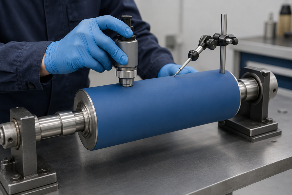
How Should Runout Be Measured?
A practical inspection method is to:
- Support the roller using its functional journals or specified datum surfaces.
- Rotate it slowly under controlled conditions.
- Measure the finished silicone outside diameter with a dial indicator or suitable noncontact system.
- Record total indicated runout at multiple axial positions.
- Check both roller ends and the center.
- Compare the measurements with the drawing tolerance.
For soft silicone, gauge contact force can deform the surface and distort the result. The measurement method, contact tip and instrument force should therefore be agreed upon when tight tolerances are required.
Parameters That Should Be Specified Separately
A complete roller drawing may include:
- Afmeting buitendiameter
- Outside-diameter tolerance
- Face length
- Radial runout or TIR
- Cylindricity
- Straightness
- Crown, taper or profile
- Journal diameter and fit
- Journal-to-journal alignment
- Surface roughness
- Edge radius or chamfer
- Dynamic balance requirement
Do not assume that diameter tolerance automatically controls runout. They are separate characteristics.
Crowned Rollers
Some rollers are intentionally larger at the center to compensate for shaft deflection and maintain a more uniform pressure distribution across the working face.
For a crowned roller, the drawing should define:
- Maximum crown height
- Crown profile
- Reference diameter
- Measurement positions
- Allowed profile deviation
A crowned surface should not be rejected as out of cylindrical tolerance if the crown is an intentional functional feature.
Runout and Dynamic Balance Are Different
Low radial runout does not guarantee good dynamic balance. A roller can be geometrically accurate but still contain an uneven mass distribution caused by:
- Nonuniform core wall thickness
- Internal welds
- Keyways
- Uneven rubber distribution
- Metal plugs or inserts
- Local grinding corrections
Dynamic balancing becomes increasingly important as roller mass, diameter and operating speed increase. If required, the drawing should define the operating speed, balance quality requirement and balancing condition.
ISO 21940-11 provides procedures and unbalance tolerances for rotors with rigid behavior. Long or flexible rollers may require additional engineering analysis because shaft deflection can dominate running performance.
Rubber-to-Metal Bonding Strength
The silicone covering must remain attached during repeated compression, acceleration, braking, heating and cleaning. Bond failure can begin as a small lifted edge and progress into complete delamination.
Important bonding variables include:
- Metal alloy
- Surface cleanliness
- Surface roughness
- Oxide condition
- Primer or bonding-agent selection
- Primer application thickness
- Time between preparation and molding
- Silicone cure chemistry
- Cure temperature and pressure
- Voorwaarden voor de nabehandeling
- Dikte van de bekleding
- Edge geometry
- Operating temperature and chemicals
Typical Metal Surface Preparation Process
A controlled bonding process may include:
- Degreasing
Removes machining oil, fingerprints and processing residue. - Mechanical surface treatment
Abrasive blasting or controlled roughening increases surface area and helps create mechanical anchoring. - Final cleaning
Removes loose abrasive, dust and contamination. - Chemical treatment when required
Aluminum, stainless steel and plated surfaces may require application-specific treatment. - Primer or bonding-agent application
A compatible primer is applied in a controlled, uniform layer. - Drying and controlled storage
Prepared cores should be protected from moisture, dust and recontamination. - Silicone molding or vulcanization
Cure time, temperature and pressure are controlled according to the compound and bonding system.
Skipping or poorly controlling any of these stages can reduce bond durability.
Mechanical Locking Features
Chemical adhesion may be supplemented with mechanical retention features, especially on rollers exposed to high torque or severe thermal cycling.
Possible features include:
- Ondiepe groeven
- Knurled surfaces
- Perforations
- Ondersnijdingen
- Recessed end areas
- Retaining shoulders
- End flanges
These features should not create sharp corners that concentrate stress or cut into the silicone during repeated deformation.
Mechanical locking is an additional safeguard; it should not be used to hide an uncontrolled chemical bonding process.
How Is Bonding Strength Tested?
ASTM D429 contains several methods for evaluating rubber adhesion to rigid substrates, including metal. Depending on specimen geometry, the methods can evaluate stripping, tension or shear-related bond behavior.
For custom rollers, testing may include:
- Representative laboratory rubber-to-metal coupons
- Peel or strip specimens made with the production bonding process
- Destructive cut-and-peel tests on qualification samples
- Torque testing
- Thermal-aging followed by adhesion testing
- Chemical exposure followed by adhesion testing
- Repeated nip-load or rotational endurance testing
ASTM D429 test specimens do not always reproduce the geometry and stress state of a finished roller. For this reason, coupon testing should be combined with finished-part inspection and application-based validation.
Adhesive Failure vs Cohesive Failure
The failure surface provides valuable information:
- Adhesive failure: silicone separates cleanly from the metal or primer interface.
- Cohesive failure: the silicone tears while rubber remains bonded to the metal.
- Mixed failure: both adhesive separation and rubber tearing occur.
A high measured force with substantial adhesive failure may still indicate an unstable bonding process. Qualification criteria should consider both the measured force and the failure mode.
Silicone Roller Manufacturing Process
A typical production route includes:
- Review the application and drawing.
- Machine and inspect the metal core.
- Check journal alignment and core straightness.
- Clean and prepare the bonding surface.
- Apply the specified primer or bonding agent.
- Mold, wrap or cast the silicone covering.
- Cure and post-cure as required.
- Rough-machine the rubber surface.
- Precision-grind the outside diameter.
- Produce grooves, crown or special surface patterns.
- Inspect hardness, dimensions and runout.
- Perform bonding and balance tests when specified.
- Clean and package the finished roller.
Grinding the silicone after curing is normally important when the application requires accurate diameter, runout and surface finish.
Surface Finish and Roller Profile
The correct surface finish depends on the roller’s function.
A smooth ground or polished surface may be required for:
- Thin-film transport
- Printing
- Laminating
- Optical material handling
- Release applications
A textured, grooved or patterned surface may be used to:
- Improve traction
- Release trapped air
- Drain liquid
- Reduce contact area
- Guide a belt or web
- Control coating thickness
Possible profiles include:
- Smooth cylindrical surface
- Axial grooves
- Spiral grooves
- Ruitpatronen
- Concave or convex profiles
- Center crown
- Stepped diameter
- Special molded textures
The drawing should identify whether surface roughness is a mandatory acceptance value or only a functional reference.
Recommended Inspection Plan
1. Metal Core Inspection
Check:
- Core material
- Outside diameter
- Wanddikte
- Shaft and journal dimensions
- Straightness
- Journal runout
- Weld condition
- Surface-preparation area
2. Material Verification
Record:
- Siliconenkwaliteit
- Kleur
- Batch number
- Cure system
- Hardness specification
- Mixing and molding date
- Omstandigheden na het uitharden
3. Hardness Inspection
Measure hardness at agreed axial and circumferential positions. When direct measurement is unreliable, use a representative test plaque from the same batch.
4. Dimensional Inspection
Check:
- Finished diameter
- Face length
- Silicone thickness
- Edge dimensions
- Groove geometry
- Crown or profile
ASTM D3767 provides practices for measuring dimensions of rubber products and notes that instrument pressure can significantly affect measurements of soft materials.
5. Runout Inspection
Measure TIR relative to the specified journal or shaft datum at multiple locations across the roller face.
6. Surface Inspection
Look for:
- Bubbels
- Pinholes
- Cuts
- Grinding lines
- Verontreiniging
- Exposed metal
- Uneven edges
- Surface waviness
- Local hardness variation
7. Bond Inspection
Inspect both roller ends for lifting, gaps or exposed bond lines. Perform destructive testing on qualification samples or production coupons when required.
8. Dynamic Balance
Balance the finished roller when operating speed, mass or equipment sensitivity requires it.
Common Failure Modes and Corrective Actions
| Failure mode | Possible cause | Corrective action |
| Silicone separates from the core | Contamination, incorrect primer or incomplete cure | Improve cleaning, surface preparation and bonding-process control |
| Excessive vibration | High runout, bent core or mass imbalance | Check journals, regrind the cover and perform dynamic balancing |
| Uneven pressure | Incorrect crown, shaft deflection or hardness variation | Review roller stiffness, profile and hardness uniformity |
| Rapid surface wear | Wrong compound, excessive slip or abrasive contamination | Select a more suitable compound and review pressure and speed |
| Roller becomes permanently flat | Excessive compression, high temperature or poor compression set | Reduce load or select a more suitable silicone formulation |
| Silicone cracks at the ends | Sharp edge, excessive cover thickness change or peeling stress | Add radii and improve edge-transition geometry |
| Surface becomes sticky | Chemical attack, overheating or unsuitable formulation | Confirm operating temperature and chemical compatibility |
| Diameter changes during use | Thermal expansion, swelling or incomplete post-cure | Validate material under actual operating conditions |
What Information Should Be Included in an RFQ?
To receive an accurate quotation, buyers should provide:
- Roller drawing or 3D model
- Finished roller outside diameter
- Working-face length
- Total shaft length
- Core and shaft material
- Journal dimensions and tolerances
- Silicone thickness
- Required Shore A hardness
- Hardness tolerance
- Kleur
- Oppervlakteafwerking
- Smooth, grooved or crowned profile
- Radial runout or TIR requirement
- Dynamic balance requirement
- Maximum rotation speed
- Applied load or nip pressure
- Bedrijfstemperatuur
- Contact materials
- Chemicals and cleaning agents
- Electrical or antistatic requirements
- Food-contact or regulatory requirements
- Verwachte levensduur
- Bestelhoeveelheid
- Annual demand
- New core or recoating requirement
Photos of the machine and failed rollers can also help the manufacturer identify potential design problems.
New Roller Manufacturing vs Roller Recoating
Existing metal cores can sometimes be stripped and recoated. Recoating may reduce cost, but the core must first be inspected for:
- Shaft bending
- Journal wear
- Corrosion
- Cracks
- Damaged threads or keyways
- Previous bonding-agent residue
- Insufficient wall thickness
- Poor weld quality
If the journals are worn or the core is bent, applying a new silicone covering will not correct the underlying rotational error.
Veelgestelde vragen
What Shore A hardness is best for a silicone roller?
There is no single best hardness. Soft rollers improve conformity and contact area, while harder rollers reduce deformation and provide greater dimensional stability. Load, cover thickness, speed and contact material must be considered together.
Can silicone be bonded directly to stainless steel?
Yes, but reliable bonding normally requires controlled cleaning, surface preparation and a compatible primer or bonding system. Stainless-steel grade and surface condition should be identified before production.
What is the difference between concentricity and runout?
Concentricity describes alignment between centers or axes. Runout measures how much a surface moves relative to a datum axis during rotation. For roller inspection, radial runout or TIR relative to the functional journals is often the more practical specification.
Can a silicone roller have low runout but still vibrate?
Yes. Low runout controls geometric rotation but does not guarantee uniform mass distribution. High-speed or heavy rollers may also require dynamic balancing.
How is silicone-to-metal adhesion verified?
Adhesion can be evaluated using representative coupons, ASTM D429 test methods, destructive peel inspection and finished-roller endurance testing. Both bond strength and failure mode should be recorded.
Can grooves be added to the silicone surface?
Yes. Axial, spiral, diamond and application-specific grooves can be molded, machined or ground into the surface. Groove width, depth, pitch and direction should be defined on the drawing.
Can old metal rollers be recoated?
Yes, provided the core, journals and shafts remain within acceptable dimensional and structural limits. The old rubber and bonding layer must be removed before the surface is prepared again.
What causes silicone roller delamination?
Common causes include oil contamination, incorrect primer, insufficient curing, incompatible materials, sharp edge geometry, excessive torque, chemical exposure and repeated thermal cycling.
Conclusie
A reliable silicone-coated metal roller requires more than selecting a silicone hardness. Buyers should define the complete relationship between the silicone covering, metal core and functional rotational axis.
The most important purchasing requirements are:
- Application-appropriate silicone formulation
- Defined Shore A hardness and cover thickness
- Finished diameter and runout relative to the journals
- Controlled surface finish or roller profile
- Validated rubber-to-metal bonding process
- Dynamic balance when required
- Inspection under realistic operating conditions
For a custom quotation, send the roller drawing together with the required hardness, dimensions, TIR, surface profile, operating temperature, speed, load and contact medium. Complete application information allows the manufacturer to recommend a practical material and inspection plan before tooling or production begins.
 English
  Japanese
  Korean
  German
  French
  Italian
  Spanish
  Dutch
Dutch  Chinese
  Portuguese
  Polish
  Czech
Czech  Hungarian
  Swedish
  Finnish
  Vietnamese
  Thai
Thai  Turkish
  Arabic
  Russian