
A silicone gasket may look like one of the simplest components in an enclosure.
However, many sealing failures are caused not by the silicone material itself, but by incorrect gasket and groove design.
Common problems include:
- insufficient gasket compression;
- excessive compression;
- groove too narrow;
- groove too deep;
- gasket rolling or moving during assembly;
- uneven bolt loading;
- excessive compression set;
- insufficient sealing pressure;
- tolerance stack-up.
A gasket can therefore be manufactured perfectly according to its drawing and still leak after assembly.
For engineers and purchasing teams developing a custom silicone sealing component, the important questions are not only:
“What Shore hardness should we use?”
They are also:
How thick should the gasket be?
How deep should the groove be?
How much should the gasket be compressed?
How wide should the groove be?
How much clamping force is required?
This guide explains the basic relationship between silicone gasket dimensions, groove geometry, compression and sealing pressure.
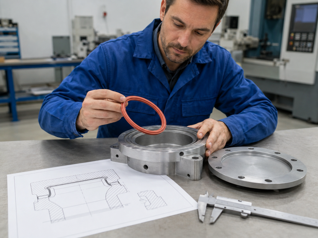
How Does a Silicone Gasket Create a Seal?
An elastomer gasket normally seals by being compressed between two mating surfaces.
Before assembly, the gasket is thicker than the final installed gap.
When the housing or cover is tightened, the gasket is compressed.
This deformation creates contact pressure between:
Gasket + Housing Surface
If sufficient and reasonably uniform contact pressure is maintained around the sealing path, the gasket can block:
- water;
- dust;
- air;
- gases;
- other fluids.
The gasket therefore needs controlled deformation.
Too little compression may leave leakage paths.
Too much compression can cause:
- excessive assembly force;
- permanent deformation;
- tearing;
- extrusion;
- accelerated compression set.
Correct gasket design is therefore a balance between compression, material stiffness, groove volume and closure force.
What Is Gasket Compression?
For a simple face-seal gasket, compression can be expressed as:
Compression (%) = (Free Gasket Height − Installed Gap) / Free Gasket Height × 100
예를 들어:
Free gasket height:
3.00 mm
Final installed gap:
2.25 mm
Compression:
(3.00 − 2.25) / 3.00 × 100 = 25%
The gasket is therefore compressed by approximately 25% of its original height.
This calculation is simple.
Selecting the correct percentage is not.
There Is No Universal Silicone Gasket Compression Percentage
A common mistake is specifying:
“All silicone gaskets should be compressed 25%.”
Real gasket design depends on:
- solid or sponge silicone;
- Shore hardness;
- gasket cross-section;
- sealing pressure;
- groove geometry;
- temperature;
- mating-surface tolerance;
- bolt spacing;
- expected service life.
For O-ring-style elastomer seals, Apple Rubber gives approximately 10–40% squeeze for static seals, while dynamic seals generally use lower maximum compression.
Parker’s O-ring engineering data also shows that compression level has a strong relationship with compression set; in one set of elastomer test data, favorable permanent-deformation behavior occurred around the 25–30% compression region. That result should not be interpreted as a universal gasket-design target because compound, section size, temperature and application all matter.
For custom molded rectangular gaskets, the supplier should evaluate the actual section rather than blindly applying an O-ring table.
Solid Silicone vs Silicone Sponge
Before designing the groove, first identify which type of silicone seal is being used.
Solid Silicone Rubber
Solid silicone is commonly used when the application requires:
- water sealing;
- high durability;
- relatively high contact pressure;
- thin precision gasket sections;
- molded sealing lips;
- immersion resistance.
Typical hardness might include:
- 30 Shore A;
- 40 Shore A;
- 50 Shore A;
- 60 Shore A;
- 70 Shore A.
Stockwell Elastomerics lists solid silicone gasket materials across roughly 10–70 Shore A depending on the formulation and application.
Solid silicone generally requires more closure force than soft cellular silicone.
Silicone Sponge
Closed-cell silicone sponge contains a cellular structure.
It is frequently selected for:
- environmental enclosure seals;
- electronics;
- cabinet doors;
- low closure-force applications;
- irregular mating surfaces.
Unlike solid silicone, sponge materials are often characterized by Compression Force Deflection (CFD) rather than Shore A hardness alone.
Stockwell notes that closed-cell sponge gaskets are commonly designed around approximately 20–35% deflection for effective sealing, while very high compression can damage the cell structure and reduce recovery.
Rogers likewise notes that appropriate compression depends on the application and material, with some cellular gasket designs using approximately 25–35% as a practical design region.
Therefore:
Solid silicone design ≠ silicone sponge design.
Always use the compression-force data for the specific material being purchased.
What Is a Gasket Groove?
A gasket groove is the channel in the housing that positions and supports the gasket.
It can control:
- gasket location;
- compression;
- lateral movement;
- assembly repeatability.
Typical groove parameters include:
- groove depth;
- groove width;
- corner radius;
- groove tolerance.
A well-designed groove can make gasket assembly much more reliable than simply placing a loose gasket between two flat surfaces.
Groove Depth Determines Compression
For a simple gasket installed into a groove and compressed by a flat cover, groove depth is one of the primary dimensions controlling squeeze.
Suppose:
Gasket height = 3.00 mm
Desired nominal compression = 25%
The target compressed height would be:
3.00 × (1 − 0.25) = 2.25 mm
So a simplified nominal groove depth could be approximately:
2.25 mm
provided the final mechanical stop is actually defined by the mating housing surfaces.
This is only the nominal calculation.
Tolerance must also be considered.
Never Design Groove Depth From Nominal Dimensions Alone
Assume:
Gasket height:
3.00 ±0.15 mm
Groove depth:
2.25 ±0.10 mm
The nominal compression is 25%.
But the actual production extremes differ.
Minimum Compression Condition
Smallest gasket:
2.85 mm
Deepest groove:
2.35 mm
Compression:
(2.85 − 2.35) / 2.85 ≈ 17.5%
Maximum Compression Condition
Largest gasket:
3.15 mm
Shallowest groove:
2.15 mm
Compression:
(3.15 − 2.15) / 3.15 ≈ 31.7%
So a “25% compression design” may actually operate from approximately:
17.5% to 31.7%
once manufacturing tolerances are included.
This is why gasket thickness tolerance and housing machining tolerance must be analyzed together.
Design Around Minimum and Maximum Compression
A better engineering process is:
Step 1: Determine minimum compression required to create the seal.
Step 2: Determine maximum safe compression for the selected silicone.
Step 3: Apply gasket and groove tolerances.
Step 4: Confirm that every worst-case condition remains inside the acceptable range.
This is more reliable than simply designing around the nominal dimension.
Groove Width Matters Too
When a silicone gasket is compressed vertically, the elastomer must deform somewhere.
Because solid elastomers are nearly incompressible in volume, the section normally bulges laterally.
Therefore, a groove should not trap the gasket so tightly that there is no room for deformation.
For O-rings, Apple Rubber specifically advises that groove/gland volume must provide enough void for the seal to deform; its design guidance states that maximum O-ring volume should not exceed the minimum gland void, with approximately 90% fill used as an important worst-case check in conventional designs.
For custom rectangular silicone gaskets, the same engineering principle applies:
provide sufficient lateral space for the compressed elastomer.
However, an O-ring gland-fill percentage should not automatically be copied onto every custom gasket geometry.
What Happens If the Groove Is Too Narrow?
An excessively narrow groove can prevent the gasket from expanding laterally.
Possible consequences include:
- excessive compression force;
- gasket extrusion;
- distortion;
- uneven sealing;
- assembly difficulty.
In extreme cases, the housing may bottom out before the gasket can deform correctly.
What Happens If the Groove Is Too Wide?
A groove that is unnecessarily wide may allow the gasket to:
- move during assembly;
- roll;
- twist;
- shift away from the intended sealing path.
Therefore, groove width needs enough clearance for deformation but still enough retention to position the gasket reliably.
Groove Width Example
Suppose a molded silicone gasket has a nominal rectangular cross-section:
3.0 mm high × 3.0 mm wide
If compressed by 25%, the section height decreases.
The material tends to expand sideways.
A groove that is also exactly:
3.0 mm wide
may provide insufficient room for this deformation depending on gasket shape and corner geometry.
The tooling engineer may therefore increase groove width while maintaining the correct groove depth.
The exact width should be validated using:
- section geometry;
- material hardness;
- compression requirement;
- tolerance;
- pressure.
Groove Corners Should Not Damage the Gasket
Very sharp internal groove corners can create:
- stress concentration;
- installation damage;
- tearing.
Appropriate corner radii can improve installation and reduce localized stress.
At the same time, the corner radius should not interfere with the intended gasket seating geometry.
The correct radius depends on the gasket cross-section and manufacturing method.
Groove Retention
During assembly, a gasket may fall out or shift before the cover is installed.
Several strategies can improve retention.
These include:
- interference fit;
- dovetail-style groove;
- molded retention features;
- locating tabs;
- adhesive backing;
- molded-in-place gasket.
The best solution depends on assembly orientation and production volume.
For automated assembly, reliable gasket retention can be particularly important.
What Is Sealing Pressure?
Gasket compression percentage 그리고 sealing pressure are related, but they are not the same thing.
Compression percentage describes how far the gasket is deflected geometrically.
Sealing pressure refers to the contact stress produced between the gasket and mating surfaces.
Two gaskets compressed by exactly 25% can create very different contact forces.
예를 들어:
Gasket A
부드러운 실리콘
30 쇼어 A
25% compression
Gasket B
Firm silicone
70 쇼어 A
25% compression
Gasket B will generally require much more force to reach the same deformation.
Therefore:
Compression alone does not determine closure force.
What Determines Gasket Compression Force?
주요 요인으로는 다음이 있습니다:
- material hardness;
- gasket width;
- gasket height;
- cross-section shape;
- compression percentage;
- total gasket length;
- temperature.
Apple Rubber’s seal design data similarly identifies applied force, durometer and cross-section as key variables affecting seal compression behavior.
This is why the material’s compression-deflection data is extremely useful when calculating enclosure closure force.
Compression Force Deflection
For sponge materials, suppliers commonly provide Compression Force Deflection, or CFD.
A simplified example might state:
CFD at 25% compression = 10 psi
This means a defined material sample requires approximately that pressure to reach the stated compression under the test conditions.
The value allows engineers to estimate the required closure force.
However, CFD depends on:
- material;
- thickness;
- test method;
- compression percentage.
Always use data for the exact material and thickness wherever possible.
Estimating Closure Force
A simplified estimate can use:
Closure Force ≈ Gasket Compression Pressure × Compressed Gasket Area
Suppose a gasket has an effective compressed footprint area of:
1,500 mm²
and the material requires an average contact pressure of:
70 kPa
The approximate total compression force becomes:
70,000 N/m² × 0.0015 m² ≈ 105 N
This is a simplified calculation.
Real assemblies are affected by:
- corners;
- gasket section changes;
- bolt spacing;
- flange stiffness;
- friction;
- local deformation.
For critical sealing systems, physical testing or finite-element analysis may be appropriate.
More Compression Does Not Always Mean Better Sealing
A common assumption is:
If 20% compression seals, 40% must seal better.
That is not necessarily true.
Excessive compression can increase:
- compression set;
- assembly force;
- flange deformation;
- gasket extrusion;
- long-term stress relaxation.
Apple Rubber specifically warns that excessive squeeze can contribute to premature seal problems, while recent groove-design guidance notes that too much compression can flatten a seal and reduce its ability to recover.
The objective should therefore be:
enough compression to maintain reliable sealing, but not unnecessary over-compression.
Compression Set Matters for Long-Term Sealing
Silicone does not always return completely to its original shape after remaining compressed for a long period.
The permanent deformation is known as:
압축 영구 변형
Parker defines compression set as the amount of deformation that remains after an elastomer has been held under specified compression and temperature conditions and then released.
For a gasket, high compression set can reduce long-term contact force.
This is particularly important in:
- hot environments;
- long-life enclosures;
- equipment rarely opened;
- continuously clamped seals.
Initial Seal vs Long-Term Seal
A prototype gasket may pass a water test immediately after assembly.
That does not guarantee it will remain sealed after:
- 1,000 hours;
- repeated temperature cycling;
- years of compression.
Long-term design should consider:
- compression set;
- stress relaxation;
- thermal expansion;
- material aging.
Accelerated environmental testing may therefore be required for critical products.
Silicone Hardness and Closure Force
For solid silicone, increasing Shore hardness generally increases resistance to deformation.
A softer silicone gasket can:
- conform to irregular surfaces more easily;
- require lower closure force.
A harder gasket can:
- resist extrusion better;
- provide greater mechanical stability.
But a harder material may require significantly more clamping force.
Therefore, selecting hardness should not be based only on:
“Harder silicone is higher quality.”
Hardness should match the sealing system.
When Softer Silicone Is Useful
Lower-durometer silicone may be suitable when:
- enclosure walls are thin;
- plastic housings cannot tolerate high bolt loads;
- surfaces have greater irregularity;
- low closing force is important.
When Harder Silicone May Be Useful
Higher-durometer material can be useful when:
- internal pressure is higher;
- extrusion resistance matters;
- the seal must remain dimensionally stable;
- mechanical retention is difficult.
Apple Rubber notes that increasing elastomer hardness and reducing extrusion gaps are among the methods used to improve resistance to pressure-driven extrusion.
Internal Pressure Changes Seal Behavior
If an enclosure contains internal fluid pressure, the pressure itself acts on the gasket.
For conventional elastomer seals, differential pressure can push the seal toward the low-pressure side of the groove and help energize sealing contact, but excessive pressure combined with large clearance can force the elastomer into the gap and cause extrusion.
This means high-pressure sealing requires additional attention to:
- groove clearance;
- gasket hardness;
- extrusion gap;
- support.
A gasket designed only for dust and splash protection should not automatically be used for a pressurized fluid system.
Bolt Spacing Is Part of Gasket Design
Even a perfectly designed gasket can leak if the enclosure flange is not compressed uniformly.
Consider a rectangular cover with bolts only at the corners.
Between bolts, the cover may bend upward.
The result is:
- high compression near the screws;
- low compression between the screws.
Leaks often occur in the low-compression areas.
Therefore, gasket design should consider:
- bolt quantity;
- bolt spacing;
- flange stiffness;
- cover thickness.
Flange Stiffness Matters
A thin plastic cover may deform significantly when the screws are tightened.
A thick aluminum cover may remain much flatter.
Therefore, the same gasket can perform differently in:
Plastic Housing
versus:
Machined Aluminum Housing
The complete sealing assembly should be evaluated rather than treating the gasket as an isolated component.
Compression Stops Can Prevent Over-Compression
One effective design feature is a mechanical compression stop.
The housing or gasket design creates a hard stop that limits final closure distance.
Once the housing reaches the stop, tightening the screws further does not continue crushing the gasket.
This can improve:
- compression repeatability;
- assembly consistency;
- gasket life.
Parker notes that molded-in-place gasket designs can incorporate compression stops specifically to help protect elastomers from over-compression.
Example Compression Stop Design
Suppose:
Gasket free height:
3.0 mm
Desired installed height:
2.25 mm
A housing feature may mechanically stop the mating surfaces at approximately:
2.25 mm separation
This produces controlled nominal compression.
Without a compression stop, the final gasket height may depend too heavily on operator torque.
Screw Torque Is Not the Same as Gasket Compression
Specifying:
“Tighten screws to 2 N·m”
does not automatically guarantee correct gasket compression.
Torque is affected by:
- screw friction;
- thread condition;
- lubrication;
- housing stiffness.
Two assemblies using identical torque may produce different gasket compression.
Where sealing is critical, mechanical compression stops are often more repeatable than relying only on screw torque.
Solid Silicone Gasket Groove Example
Consider a custom rectangular solid silicone gasket.
Nominal gasket cross-section:
3.0 mm high × 4.0 mm wide
소재:
50 Shore A silicone
Target nominal compression:
25%
Nominal installed height:
2.25 mm
A preliminary groove might therefore use approximately:
2.25 mm depth
with a width greater than the gasket’s free width to allow lateral deformation.
But before releasing the design, the engineer should still calculate:
- minimum gasket thickness;
- maximum gasket thickness;
- groove depth tolerance;
- groove width tolerance;
- housing distortion;
- expected internal pressure.
The nominal dimensions alone are not enough.
Silicone Sponge Gasket Example
Consider a closed-cell silicone sponge gasket.
Free thickness:
4.0 mm
Target deflection:
30%
Installed height:
4.0 × 0.70 = 2.8 mm
Therefore, the nominal installed gap would be approximately:
2.8 mm
However, actual closure force should be taken from the selected material’s CFD curve.
Different silicone sponge grades can require dramatically different force at the same compression percentage.
Stockwell’s published sponge data, for example, shows soft and firm grades with very different compression-force ranges when tested at 25% deflection.
Solid Silicone or Sponge for Waterproofing?
There is no universal answer.
Solid silicone can provide:
- strong sealing contact;
- good immersion sealing;
- precision molded geometry.
Sponge silicone can provide:
- lower compression force;
- better conformity;
- easier sealing of irregular surfaces.
Stockwell notes that solid silicone may be preferred for some water-immersion applications when sufficient closure force and suitable fastening hardware are available.
The choice depends on enclosure design and closure force.
Groove Fill Must Include Tolerance
When evaluating groove fill, use the worst-case conditions:
Maximum Gasket Volume
versus:
Minimum Groove Volume
Do not compare nominal dimensions only.
This is especially important for continuous closed-loop gaskets where manufacturing tolerances accumulate around the perimeter.
Account for Thermal Expansion
Silicone and the housing material do not expand at the same rate.
During temperature cycling:
- aluminum changes dimension;
- plastic changes dimension;
- silicone changes dimension.
If the product operates across a large temperature range, the sealing system should be tested at both low and high temperatures.
Chemical Swelling Can Change Groove Fill
A gasket exposed to chemicals may:
- swell;
- soften;
- shrink;
- harden.
If swelling occurs inside a groove that already has very little free volume, the gasket may become overfilled.
Material compatibility should therefore be evaluated together with gland design.
Common Silicone Gasket Design Mistakes
Groove Too Deep
Results in insufficient compression and possible leakage.
Groove Too Shallow
Produces excessive compression and high assembly force.
Groove Too Narrow
Provides insufficient deformation volume.
No Tolerance Analysis
Nominal compression looks correct, but worst-case production parts fail.
Excessive Bolt Spacing
Creates low-pressure regions between fasteners.
Wrong Silicone Hardness
Housing cannot provide enough compression force.
Ignoring Compression Set
Initial testing passes but long-term sealing degrades.
Using O-Ring Rules for Every Custom Gasket
Rectangular, lip and sponge gaskets need geometry-specific evaluation.
What Should Be on a Silicone Gasket Drawing?
A useful drawing should include:
| Requirement | Example |
|---|---|
| 자료 | Platinum-Cured Silicone |
| 경도 | 50 ±5 Shore A |
| Cross-Section | 3.0 × 4.0 mm |
| Critical Height | 3.00 ±0.10 mm |
| Groove Depth | Defined on Housing Drawing |
| Target Compression | Design requirement |
| 플래시 | Controlled on sealing surfaces |
| Joint | Continuous molded loop |
| 색상 | 검정 |
| 신청 | Environmental enclosure seal |
The gasket drawing and housing groove drawing should be reviewed together.
What Information Should You Send the Silicone Manufacturer?
For a custom gasket RFQ, provide:
- gasket 3D CAD;
- gasket 2D drawing;
- housing groove CAD;
- mating cover drawing;
- silicone grade;
- Shore hardness;
- operating temperature;
- internal/external pressure;
- sealed medium;
- required IP or leak performance;
- annual quantity.
This allows the silicone manufacturer to review the seal as a complete system.
Ask for DFM Before Cutting the Mold
Before production tooling begins, request a Design for Manufacturability review.
The supplier should evaluate:
- gasket cross-section;
- mold parting line;
- flash location;
- gate location;
- demolding;
- critical tolerances.
For sealing components, the supplier should also understand the intended compression.
A 3.0 mm gasket designed to operate at a 2.2 mm gap is fundamentally different from the same gasket used at a 2.8 mm gap.
Prototype the Actual Assembly
The most meaningful validation test is not simply measuring the gasket.
테스트:
Gasket + Actual Groove + Actual Housing + Actual Fasteners
Depending on the application, validation may include:
- water immersion;
- pressure decay;
- vacuum leak testing;
- IP testing;
- thermal cycling;
- aging;
- repeated opening and closing.
Test Worst-Case Tolerances
Prototype testing should ideally include combinations representing:
Minimum Compression
Thin gasket + deep groove.
Maximum Compression
Thick gasket + shallow groove.
This gives much better confidence than testing only nominal parts.
Silicone Gasket Design Checklist
Before releasing a custom gasket design, confirm:
- solid or sponge silicone;
- gasket material;
- hardness or CFD grade;
- free gasket height;
- groove depth;
- groove width;
- minimum compression;
- nominal compression;
- maximum compression;
- tolerance stack-up;
- groove fill;
- internal pressure;
- extrusion clearance;
- bolt spacing;
- flange stiffness;
- compression stops;
- operating temperature;
- fluid compatibility;
- compression set;
- required leak or IP performance.
A gasket should not be designed independently from the enclosure.
결론
Successful silicone gasket design depends on much more than selecting the correct rubber hardness.
The critical relationship is:
Gasket Cross-Section + Groove Geometry + Compression + Closure Force + Housing Design
Groove depth largely determines gasket compression.
Groove width must provide enough space for elastomer deformation.
Material hardness and cross-section determine how much closure force is required.
And long-term sealing depends not only on initial compression but also on:
- compression set;
- tolerance;
- temperature;
- pressure;
- flange stiffness.
General design guides may suggest useful starting ranges—for example, static O-ring guidance commonly spans approximately 10–40% compression, while many closed-cell sponge gasket designs operate around 20–35% deflection—but these ranges should never replace application-specific engineering and validation.
For custom silicone gaskets, the most reliable approach is:
define the sealing requirement → choose the material → calculate compression → design the groove → evaluate tolerance → verify closure force → test the actual assembly.
This results in a much more reliable seal than selecting a gasket thickness independently and adjusting the groove later.
자주 묻는 질문
실리콘 개스킷은 어느 정도까지 압축되어야 하나요?
There is no universal percentage. The correct compression depends on whether the gasket is solid or cellular, its hardness, cross-section, sealing pressure and service conditions. Static elastomer sealing references may use a broad range around 10–40% as a starting point, while closed-cell sponge materials often operate in a narrower deflection range. Always verify the specific material.
How do I calculate the groove depth for a silicone gasket?
For a simple face seal, start from the gasket’s free height and desired compression. A 3.0 mm gasket compressed 25% has an installed height of approximately 2.25 mm. Then apply the gasket and groove tolerances to calculate minimum and maximum compression.
Should the groove width equal the gasket width?
Usually not exactly. The elastomer needs space to deform laterally during compression. Groove width should accommodate the compressed gasket while still retaining it securely.
Is more gasket compression always better?
No. Excessive compression can increase closure force, compression set, extrusion and permanent deformation. The goal is sufficient sealing contact with reasonable long-term strain.
Does a harder silicone gasket provide a better seal?
Not necessarily. Harder silicone can improve mechanical stability and extrusion resistance, but it normally requires greater clamping force. Softer silicone can conform more easily to imperfect mating surfaces.
Should I use solid silicone or silicone sponge for an enclosure gasket?
Solid silicone is useful where higher sealing contact pressure and precision geometry are needed. Silicone sponge is useful when low closure force and conformity are important. The housing stiffness, fastener arrangement and environmental requirements should determine the final choice.
 English
  Japanese
  Korean
  German
  French
  Italian
  Spanish
  Dutch
Dutch  Chinese
  Portuguese
  Polish
  Czech
Czech  Hungarian
  Swedish
  Finnish
  Vietnamese
  Thai
Thai  Turkish
  Arabic
  Russian