
When sourcing a custom silicone rubber component, one of the most common questions from engineers and purchasing teams is:
“How tight can the dimensional tolerance be?”
A drawing may specify ±0.05 mm, ±0.10 mm, or ±0.20 mm tolerances, but silicone rubber does not behave like machined aluminum, steel, or rigid injection-molded plastic.
Silicone is flexible. It expands during molding, shrinks during curing and post-curing, and can deform during measurement. Part geometry, hardness, mold construction, parting-line location, material formulation, and molding process can all influence the final dimensions.
For this reason, specifying unnecessarily tight tolerances can significantly increase tooling cost, inspection requirements, scrap rate, and production difficulty.
This guide explains what dimensions can realistically be controlled in stampaggio personalizzato del silicone, how tolerance capability varies between different features, and what buyers should specify when requesting a quotation.
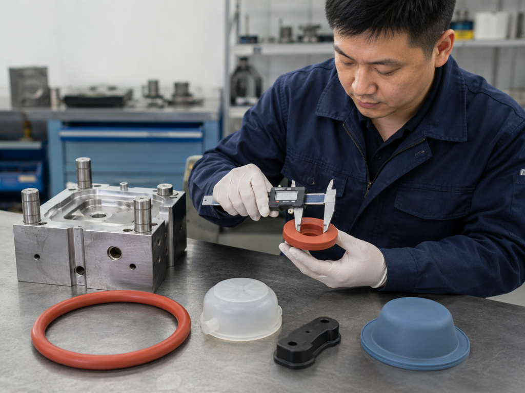
Why Silicone Rubber Tolerances Are Different From Plastic or Metal Parts
A CNC-machined metal component is produced by removing material from a dimensionally stable workpiece.
Silicone molding works differently.
Liquid or uncured silicone enters or is placed into a mold cavity, cures at elevated temperature, and then contracts as it cools. Additional dimensional changes may occur during post-curing.
The final dimensions can therefore be affected by:
- silicone material shrinkage;
- mold temperature;
- curing temperature and curing time;
- injection or compression pressure;
- mold cavity dimensions;
- number of mold cavities;
- part thickness;
- wall-thickness variation;
- part geometry;
- silicone Shore hardness;
- parting-line location;
- demolding deformation;
- post-curing;
- measurement method.
This is why every dimension on a silicone component should not automatically receive the same tight tolerance.
Instead, engineers should identify critical-to-function dimensions and apply tighter tolerances only where they are actually required.
Common Silicone Rubber Tolerance Standards
Two references are commonly encountered when specifying molded rubber dimensions.
ISO 3302-1
ISO 3302-1:2014 specifies dimensional tolerance classes for molded, extruded and calendared solid rubber products. The standard remains published and was confirmed during its latest systematic review.
It provides a useful framework for discussing achievable rubber tolerances instead of applying machining tolerances to an elastomer component.
RMA Molded Rubber Tolerances
The Rubber Manufacturers Association system traditionally divides molded rubber tolerances into classes such as:
- A1 — High Precision
- A2 — Precision
- A3 — Commercial
- A4 — Non-Critical
Higher precision generally requires better tooling, tighter material and process control, more inspection and potentially fewer cavities, which increases manufacturing cost.
For example, published RMA metric tables show that for dimensions up to 10 mm, tolerance values can range from approximately 0.10 mm for an A1 fixed dimension to much wider values for commercial or closure dimensions. As dimensions become larger, allowed variation also increases.
However, these tables should be used as design references rather than assuming every silicone component can automatically achieve the tightest class.
Actual capability should be confirmed with the molding supplier based on the specific component.
What Silicone Dimensions Are Easiest to Control?
Not every dimension has the same molding difficulty.
The most important distinction is usually between fixed dimensions e closure dimensions.
1. Fixed Mold Dimensions
A fixed dimension is normally created entirely within one half of the mold or by features that do not depend strongly on mold closing position.
Tra gli esempi figurano:
- hole diameter formed by a fixed core pin;
- internal cavity diameter;
- molded pocket dimensions;
- local rib width;
- certain internal diameters;
- dimensions between features located in the same mold half.
These dimensions are generally easier to control.
For a properly designed precision silicone mold, dimensions around:
±0.10 to ±0.20 mm
may be achievable for many small and medium-size features.
For certain small critical features, even tighter control may be possible after process validation.
But this should never be assumed without reviewing:
- part geometry;
- silicone grade;
- Shore hardness;
- mold design;
- cavity quantity;
- measurement method.
2. Mold Closure Dimensions
Closure dimensions cross the mold parting line or depend on how the two mold halves close.
Tra gli esempi figurano:
- overall component thickness;
- flange thickness across the parting line;
- height between opposite mold surfaces;
- dimensions affected by mold flash;
- dimensions created by upper and lower mold halves.
These dimensions are usually more difficult to control than fixed dimensions.
Small variations in:
- clamping force;
- mold alignment;
- material loading;
- mold temperature;
- flash formation;
- tool wear
can influence the final measurement.
Published RMA tolerance tables therefore distinguish between fixed and closure dimensions, with closure dimensions generally receiving wider tolerances.
This distinction is extremely important when designing precision silicone seals and molded components.
Typical Silicone Molding Tolerance Capability
The following ranges are useful as an initial engineering reference, not as a universal manufacturing guarantee.
| Requisito | Typical Engineering Expectation |
|---|---|
| General non-critical dimensions | ±0.3 to ±0.5 mm |
| Standard production dimensions | ±0.2 to ±0.3 mm |
| Controlled functional dimensions | ±0.10 to ±0.20 mm |
| High-precision local dimensions | Around ±0.05 to ±0.10 mm may be possible after evaluation |
| Large flexible dimensions | Usually require wider tolerances |
| Dimensions across parting lines | Usually wider than fixed mold dimensions |
A supplier should review the drawing before confirming anything tighter than normal molded rubber tolerances.
Ad esempio:
10.00 ±0.10 mm
may be realistic for a relatively rigid 60–70 Shore A silicone component molded with a stable core feature.
The same tolerance may be extremely difficult on a:
- very soft 20 Shore A part;
- 200 mm long silicone gasket;
- thin flexible membrane;
- large flat silicone sheet;
- dimension spanning the mold parting line.
The number itself does not determine manufacturing difficulty.
Geometry determines whether the tolerance is practical.
Which Dimensions Are Hardest to Control?
Large Overall Length and Width
Large silicone components accumulate more shrinkage variation.
For example, controlling a 5 mm feature to ±0.10 mm is fundamentally different from controlling a 300 mm overall dimension to the same ±0.10 mm.
The percentage variation becomes much more demanding.
Large:
- gaskets;
- covers;
- membranes;
- silicone frames;
- molded sheets
therefore generally require larger absolute tolerances.
Thin Wall Thickness
Very thin silicone features can be affected by:
- mold filling;
- venting;
- flash;
- material flow;
- local pressure;
- curing conditions.
For LSR components, thin walls can often be molded successfully, but the dimensional tolerance must still be evaluated together with the flow path and surrounding structure.
Long Flexible Features
A long silicone tube, flap, lip or sealing edge can stretch simply from being handled.
This means measurement itself becomes a problem.
A 100 mm soft silicone feature may measure differently depending on whether it is:
- lying naturally on a table;
- slightly stretched;
- compressed;
- held vertically;
- measured with a caliper.
For flexible silicone components, the measurement method should therefore be defined together with the tolerance.
Silicone Hardness Affects Dimensional Measurement
Silicone hardness has a major influence on dimensional stability.
A 70 Shore A silicone component is relatively firm.
A 20–30 Shore A component can deform considerably under very small measurement forces.
For soft parts, conventional calipers can compress the silicone and produce an incorrect reading.
Depending on the component, inspection may therefore use:
- optical measuring systems;
- vision measurement;
- profile projectors;
- CMM fixtures;
- go/no-go gauges;
- customized inspection fixtures;
- controlled low-force gauges.
For high-precision projects, buyers should discuss how the dimension will be measured, not only the nominal dimension and tolerance.
Material Shrinkage Must Be Considered in Mold Design
Silicone does not leave the mold at exactly the same dimensions as the mold cavity.
The tooling engineer must compensate for material shrinkage.
Shrinkage depends on factors including:
- silicone formulation;
- platinum-cured or peroxide-cured system;
- filler content;
- molding temperature;
- curing conditions;
- post-curing;
- geometry;
- material flow direction.
Therefore, a mold should not simply be manufactured by copying the final CAD dimensions directly.
During mold development, appropriate shrinkage compensation is applied to the cavity dimensions.
For demanding projects, first samples are measured and tooling dimensions may then be adjusted before mass production.
LSR Injection Molding vs Compression Molding Tolerance
Both processes can manufacture accurate silicone components, but their process characteristics differ.
Liquid Silicone Rubber Injection Molding
LSR injection molding is particularly suitable for:
- high-volume components;
- medical silicone parts;
- electronic seals;
- precision connectors;
- small complex components;
- multi-cavity production;
- silicone overmolding.
Advantages for dimensional consistency include:
- automatic material metering;
- controlled mixing;
- repeatable injection volume;
- controlled mold temperature;
- automated production cycles.
Once the process is validated, LSR molding can provide excellent repeatability.
Stampaggio a compressione
Compression molding remains widely used for:
- industrial silicone seals;
- larger components;
- lower-volume projects;
- simple molded parts;
- prototypes;
- custom rubber components.
However, dimensional variation may be influenced more strongly by:
- material charge weight;
- operator handling;
- compression pressure;
- material positioning;
- flash thickness.
Compression molding can still achieve good precision, but extremely tight tolerances may require additional process control.
Parting Line Location Matters
One of the most overlooked tolerance issues in silicone component design is the parting line.
Suppose a customer specifies:
Thickness: 3.00 ±0.05 mm
If that dimension is created between the two mold halves, it is a closure dimension.
Maintaining ±0.05 mm may require considerably more effort than achieving the same tolerance on a feature formed entirely by a fixed mold insert.
A good silicone manufacturer will therefore review:
- mold opening direction;
- parting line;
- core design;
- ejecting method;
- flash location
before confirming tolerance capability.
Sometimes modifying the mold structure can make an important dimension easier to control without changing the function of the product.
Don’t Apply ±0.1 mm to Every Dimension
This is one of the most common problems we see in customer drawings.
A drawing may contain 30 dimensions, with every dimension specified as:
±0.10 mm
Usually, only three or four dimensions actually affect assembly or function.
Applying high precision to all 30 dimensions can result in:
- higher mold cost;
- slower production;
- more inspection;
- lower yield;
- more rejected parts;
- longer development cycles.
Instead, divide dimensions into categories.
Critical Dimensions
Esempi:
- sealing diameter;
- connector interface;
- hole position;
- mating surface;
- insert position.
These may receive tighter tolerances.
Functional but Non-Critical Dimensions
These dimensions need reasonable consistency but do not directly determine assembly.
Normal molded silicone tolerances are usually sufficient.
Cosmetic Dimensions
Dimensions that primarily affect appearance should generally receive wider tolerances unless there is a specific functional reason.
Tolerance Stack-Up in Silicone Assemblies
Tolerance becomes even more important when silicone components interact with rigid parts.
For example, consider a silicone seal installed between:
- an aluminum housing;
- a plastic cover;
- a silicone gasket.
Each component has its own dimensional variation.
If designers consider only the silicone gasket tolerance, the final compression may still be incorrect.
A proper tolerance analysis should consider:
Housing tolerance + gasket tolerance + cover tolerance + assembly variation
Ciò è particolarmente importante per:
- waterproof seals;
- battery enclosures;
- automotive connectors;
- sensor housings;
- medical devices;
- electronic housings.
For a sealing application, compression ratio and interference are often more important than achieving an unnecessarily precise free-state silicone dimension.
Hole Diameter and Hole Position Tolerance
Small molded holes are common in silicone components.
Tra gli esempi figurano:
- valve holes;
- cable openings;
- mounting holes;
- ventilation holes;
- connector openings.
Hole diameter can often be controlled relatively well when formed by a stable mold pin.
Hole position depends on the surrounding mold geometry and the overall deformation of the component.
For very small precision holes, manufacturers may also consider:
- molded holes;
- mechanical punching;
- laser processing;
- secondary trimming.
The best process depends on hole diameter, quantity, wall thickness and required tolerance.
Silicone Overmolding Tolerances
Tolerance analysis becomes more complicated when silicone is molded onto:
- metal inserts;
- plastic housings;
- electronic components;
- stainless steel components;
- aluminum parts.
The final dimensional accuracy depends not only on silicone shrinkage but also on:
- insert tolerance;
- insert positioning;
- fixture accuracy;
- mold location features;
- silicone shrinkage;
- insert movement during molding.
If the insert itself has ±0.10 mm dimensional variation, demanding ±0.05 mm on the final silicone-to-insert position may be unrealistic.
The entire tolerance chain must be evaluated.
What Should Buyers Put on the Drawing?
For custom silicone projects, a good RFQ drawing should contain:
1. Nominal dimensions
Example:
25.00 mm
2. Critical tolerances
Example:
25.00 ±0.10 mm
Only specify tight tolerances where necessary.
3. Silicone hardness
Ad esempio:
50 ±5 Shore A
4. Material requirement
Esempi:
- food-grade silicone;
- medical-grade LSR;
- platinum-cured silicone;
- high-temperature silicone;
- flame-retardant silicone.
5. Color
Pantone or physical color sample can be supplied if color consistency is important.
6. Surface requirement
Esempi:
- matte;
- polished;
- textured;
- mold finish;
- no visible flow marks.
7. Flash requirement
Flash limits can be important around:
- sealing surfaces;
- valve edges;
- optical areas;
- mating interfaces.
8. Inspection requirement
Indicate whether inspection requires:
- dimensional report;
- first article inspection;
- CPK study;
- cavity-by-cavity measurement;
- material certificate;
- incoming inspection data.
Example: How to Specify Tolerances More Efficiently
Instead of writing:
All dimensions ±0.10 mm
consider something like:
| Caratteristica | Requisito |
| Seal OD | 25.00 ±0.10 mm |
| Mounting holes | Ø3.00 ±0.10 mm |
| Hole position | ±0.15 mm |
| Lunghezza totale | ±0.30 mm |
| Larghezza totale | ±0.30 mm |
| Non-critical dimensions | General molded tolerance |
| Shore hardness | 50 ±5 Shore A |
This approach focuses manufacturing resources on the features that actually determine product performance.
Can Silicone Parts Hold ±0.05 mm?
Sometimes.
But the correct question should be:
“Which specific feature needs ±0.05 mm, and why?”
A localized feature formed by a precision mold insert may be much easier to control than the overall length of a soft silicone component.
Achieving ±0.05 mm may require:
- precision mold machining;
- stable silicone formulation;
- optimized shrinkage compensation;
- controlled process parameters;
- limited cavity variation;
- specialized measurement;
- tool correction after sampling;
- statistical process monitoring.
Therefore, ±0.05 mm should normally be reserved for genuinely critical features.
Designing for Stable Silicone Dimensions
Several design decisions can improve dimensional repeatability.
Keep Wall Thickness Consistent
Large thickness transitions can cause uneven curing and shrinkage.
Gradual transitions are generally preferable.
Avoid Extremely Long Unsupported Features
Long flexible structures are difficult to measure and control.
Add structural support where possible.
Position Critical Features Carefully
Whenever possible, design important dimensions so that they are controlled within a stable mold feature instead of across a mold parting line.
Use Appropriate Hardness
Extremely soft silicone may be necessary for sealing or tactile performance, but softer materials naturally deform more during inspection and assembly.
Define Functional Requirements
Sometimes compression, sealing force or fit is more important than the free-state dimension.
Specifying the true functional requirement allows the manufacturer to recommend a more manufacturable tolerance.
Why Prototype Measurements May Differ From Mass Production
Prototype silicone parts are sometimes manufactured using different tooling or processes than production components.
Ad esempio:
- prototype mold;
- single-cavity mold;
- compression molding;
- soft tooling.
Mass production may later use:
- hardened steel tooling;
- multi-cavity molds;
- automated LSR injection;
- controlled post-curing.
Therefore, dimensional capability confirmed during prototype development should be validated again when production tooling is introduced.
First Article Inspection Is Important for Precision Silicone Parts
For tolerance-sensitive projects, first article inspection can verify:
- critical dimensions;
- hole location;
- wall thickness;
- insert position;
- overall geometry;
- Shore hardness;
- appearance.
If deviations are found, the mold can sometimes be corrected before full production begins.
For multi-cavity molds, measurements should also consider cavity-to-cavity variation, not simply inspect one random component.
A Practical Rule for Silicone Tolerance Design
When designing custom silicone rubber parts, use the following principle:
Tight tolerance where function requires it; standard molded tolerance everywhere else.
This approach normally provides the best balance between:
- dimensional accuracy;
- mold cost;
- production yield;
- inspection cost;
- lead time;
- long-term manufacturing stability.
Silicone can be molded with excellent repeatability, particularly with well-designed LSR injection tooling, but treating a flexible elastomer like a CNC-machined metal component often creates unnecessary manufacturing problems.
Custom Silicone Molding Tolerance Checklist
Before sending an RFQ, confirm the following:
- What dimensions directly affect assembly?
- Which dimensions affect sealing?
- Which dimensions are cosmetic only?
- Is the dimension across a mold parting line?
- What silicone hardness is required?
- Is the part extremely soft or flexible?
- Are there thin membranes or long unsupported features?
- Are inserts being overmolded?
- È necessario un post-indurimento?
- How will critical dimensions be measured?
- Is a first article dimensional report required?
- Does production require CPK or statistical process control?
Providing this information allows the silicone manufacturer to determine whether the requested tolerances are realistic before tooling begins.
Conclusione
There is no single tolerance value that applies to every custom silicone rubber component.
A small fixed feature in a precision LSR mold may be controlled very accurately, while a large flexible dimension or mold-closure dimension may require considerably wider tolerance.
International references such as ISO 3302-1 provide dimensional tolerance classes for molded rubber products, while RMA tolerance classifications provide another widely used engineering reference for communication between buyers and manufacturers.
For most projects, the best approach is not to specify the tightest possible tolerance everywhere.
Instead:
identify the critical dimensions, understand the mold structure, define the measurement method, and confirm manufacturing capability before cutting the production mold.
This results in more stable production, lower tooling costs and fewer dimensional disputes during incoming inspection.
Domande frequenti
What is a typical tolerance for custom silicone molded parts?
Many standard silicone dimensions can be designed around approximately ±0.2 to ±0.3 mm, while selected precision features may achieve approximately ±0.10 mm or tighter depending on size, geometry, material hardness and mold design. The drawing should always be reviewed before production tolerance is confirmed.
Can injection-molded LSR achieve ±0.1 mm tolerance?
Yes, ±0.1 mm can be achievable for many properly designed small features, but it should not be automatically applied to every dimension. Overall size, parting-line dimensions, very soft materials and large flexible structures may require wider tolerances.
Why are closure dimensions less accurate?
Closure dimensions depend on the relationship between two mold halves. Mold clamping, flash, material loading and tool movement can therefore introduce additional variation compared with features formed entirely by fixed mold surfaces.
Does silicone hardness affect tolerance?
Yes. Softer silicone deforms more easily during demolding, handling and inspection. As a result, both manufacturing variation and measurement repeatability must be considered.
Should every dimension on my silicone drawing have a tolerance?
Not necessarily. Tight tolerances should normally be assigned to critical assembly, sealing and functional features. Non-critical dimensions can use a general molded rubber tolerance to reduce tooling and inspection costs.
Which standard can be used for silicone rubber dimensional tolerances?
ISO 3302-1 is an international standard covering dimensional tolerance classes for molded and other solid rubber products. RMA molded-rubber tolerance classifications are also frequently referenced when discussing rubber molding capability.
 English
  Japanese
  Korean
  German
  French
  Italian
  Spanish
  Dutch
Dutch  Chinese
  Portuguese
  Polish
  Czech
Czech  Hungarian
  Swedish
  Finnish
  Vietnamese
  Thai
Thai  Turkish
  Arabic
  Russian