
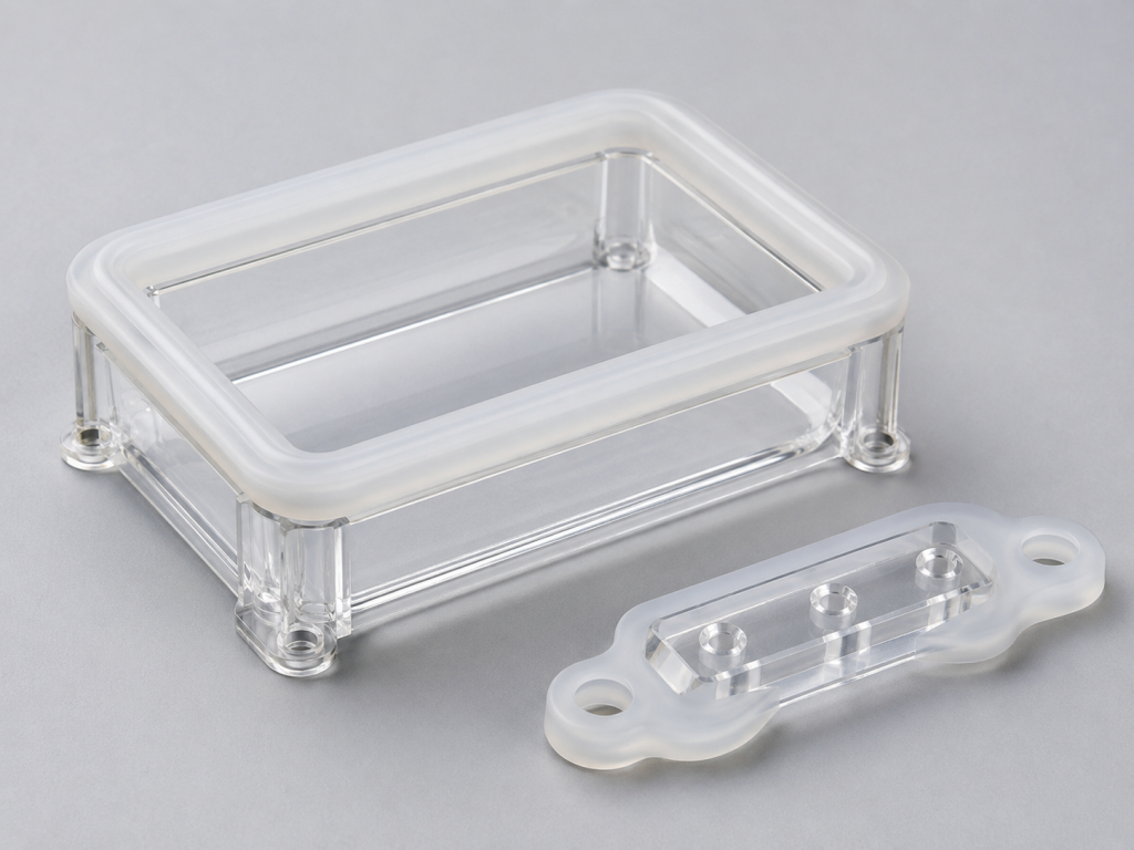
Self-bonding liquid silicone rubber overmolded onto polycarbonate can combine a rigid structural component with a flexible sealing, cushioning, gripping, or insulating surface in one integrated part.
This hard-soft combination is widely considered for medical devices, respiratory products, electronics, wearable devices, waterproof housings, optical components, automotive sensors, connectors, and fluid-handling assemblies. Polycarbonate provides the rigid supporting structure, while LSR provides elasticity, sealing performance, and a soft interface.
However, successful adhesion between LSR and PC should never be assumed.
The term “self-bonding” does not mean that every self-bonding LSR will adhere to every polycarbonate grade under all molding conditions. Adhesion depends on the exact LSR formulation, PC resin grade, additives, surface condition, mold temperature, cure time, insert temperature, joint geometry, contamination control, and post-molding environment.
Material suppliers specifically recommend testing each LSR and substrate combination before mass production because different plastic grades can have different surface properties.
This guide explains the main adhesion methods, material-selection requirements, mold-design principles, process controls, testing procedures, and common failure modes involved in self-bonding LSR-to-PC overmolding.
What Is Self-Bonding LSR?
Self-bonding LSR is a specially formulated liquid silicone rubber designed to develop adhesion to selected thermoplastics or metals during the molding and curing process.
Standard LSR generally does not create reliable chemical adhesion to untreated polycarbonate. A conventional assembly may therefore require:
- Mechanical interlocking
- A separate primer
- Plasma treatment
- An adhesive
- Secondary assembly
- Additional sealing components
Self-bonding or primerless LSR can eliminate some of these operations by bonding directly to a compatible substrate during overmolding.
Momentive defines self-bonding LSR as a material formulated to bond directly to specific substrates during molding without a primer or secondary bonding step.
The word “specific” is important. The buyer must verify that the selected LSR grade is designed and tested for the exact PC resin used in the final product.
Why Combine LSR With Polycarbonate?
Polycarbonate is commonly selected for rigid medical, electronic, industrial, and optical components. Depending on its formulation, it can offer:
- High impact resistance
- Dimensional stability
- Moldability
- Átláthatóság
- Structural rigidity
- Availability in healthcare grades
- Availability in sterilization-compatible grades
- Integration of clips, ribs, bosses, channels, and optical features
Healthcare polycarbonate grades are available with biocompatibility assessments and controlled change-management programs, but the exact grade and regional availability must be confirmed with the resin supplier.
LSR can add:
- Waterproof sealing
- Flexible valves
- Soft-touch surfaces
- Vibration isolation
- Electrical insulation
- Cushioning
- Flexible membranes
- Skin-contact interfaces
- Integrated gaskets
- Dust protection
- Pressure-responsive features
Overmolding the two materials can reduce component count and eliminate a separately installed gasket.
Common LSR-to-PC Applications
Typical two-component applications include:
- Respiratory mask frames and face seals
- Medical-device housings
- Diagnostic equipment seals
- Drug-delivery components
- Fluid-control valves
- Wearable-device housings
- Electronic buttons and membranes
- Waterproof connector bodies
- Érzékelőházak
- Lighting components
- Battery and electronics enclosures
- Optical assemblies
- Automotive radar and camera seals
- Handheld-device grips
- Reusable healthcare products
Polycarbonate overmolding with LSR is used in medical products such as respiratory masks and other devices requiring molded-in sealing features.
Main Adhesion Methods
There are four primary strategies for joining LSR to PC:
- Primerless self-bonding LSR
- Primer-assisted bonding
- Surface activation or treatment
- Mechanical interlocking
A robust design may use more than one method.
Method 1: Primerless Self-Bonding LSR
Primerless self-bonding LSR is often the preferred method for high-volume two-component molding.
The PC insert or first-shot component is positioned in the LSR mold, and the self-bonding silicone is injected directly onto the exposed bonding surface. During curing, the LSR develops adhesion to the compatible polycarbonate.
Potential advantages include:
- Fewer manufacturing steps
- No manual primer application
- Lower contamination risk
- Reduced solvent handling
- Improved automation
- Shorter production flow
- Lower assembly labor
- More consistent adhesive coverage
- Better suitability for two-shot molding
- Reduced work-in-process inventory
WACKER reports that certain self-adhesive LSR grades can bond to PC without substrate pretreatment and can support automated multicomponent production.
Momentive also offers self-bonding LSR families developed for primerless adhesion to PC and other selected thermoplastics.
Limitations of Primerless Bonding
Primerless bonding can fail when:
- The PC grade is incompatible
- The resin contains unsuitable additives
- The surface is contaminated
- The insert is too cold
- Cure time is insufficient
- The interface receives inadequate pressure
- The LSR is molded onto the wrong side of a film or coated component
- The PC has aged or absorbed contamination during storage
- The interface is subjected to peeling stress
- The mold surface becomes contaminated
- The material combination has not been validated
A successful trial with one PC grade does not prove compatibility with another grade from the same resin family.
Method 2: Primer-Assisted Bonding
A primer can be applied to the PC bonding surface before LSR molding.
The primer acts as an adhesion-promoting layer between the silicone and thermoplastic substrate.
A primer may be considered when:
- The selected LSR is not self-bonding
- Primerless adhesion is inconsistent
- The PC surface is difficult to bond
- The application requires additional adhesion margin
- The project uses an existing LSR grade
- Production volume does not justify a new material system
- Mechanical locking is limited
Silicone primers are commercially available to improve adhesion to plastics and other substrates, but compatibility must be confirmed for the selected PC and LSR system.
Primer Process Risks
Primer application introduces additional controls:
- Surface cleaning
- Application thickness
- Coverage consistency
- Drying time
- Primer shelf life
- Solvent handling
- Operator training
- Environmental controls
- Masking of nonbonding areas
- Lot traceability
- Regulatory evaluation
- Potential cosmetic marks
- Increased cycle and labor cost
Too much primer may create deposits, visible marks, weak boundary layers, or dimensional variation.
Too little primer may leave unbonded areas.
For medical or food-contact products, every primer and solvent must be included in the material and regulatory assessment.
Method 3: Surface Activation
Surface treatment can increase surface energy and improve adhesion in selected systems.
Potential methods include:
- Atmospheric plasma
- Low-pressure plasma
- Corona treatment
- Flame treatment
- UV-ozone treatment
- Chemical surface treatment
Plasma treatment is used in some silicone bonding systems to improve adhesion where untreated substrate bonding is insufficient.
However, surface activation is time-sensitive. The treated surface may gradually lose its activated condition before overmolding.
A validated process should define:
- Treatment method
- Power
- Gas
- Distance
- Treatment speed
- Number of passes
- Maximum delay before molding
- Storage environment
- Surface-cleanliness requirements
- Inspection or monitoring method
Surface treatment should not be added without a controlled validation plan.
Method 4: Mechanical Interlocking
Mechanical interlocking uses the shape of the PC component to physically retain the cured silicone.
Common features include:
- Through-holes
- Nyerőgépek
- Undercuts
- Grooves
- Windows
- Perforations
- Retention ribs
- Dovetail features
- Wraparound edges
- Captured flanges
- Enlarged anchor pockets
The LSR flows through or around these features and becomes mechanically locked after curing.
Mechanical interlocking is useful when:
- Chemical adhesion is uncertain
- The application experiences peel stress
- The bond is safety-critical
- The product undergoes repeated flexing
- The interface contacts water or chemicals
- Long-term aging may reduce adhesion
- The design requires a redundant retention method
Mechanical locking can support the chemical bond, but it should not compensate for an uncontrolled molding process.
Material Pairing Is the First Design Decision
The LSR and PC grades should be selected as a tested material pair.
Do not choose the PC based only on its mechanical properties and choose the LSR separately at a later stage.
The evaluation should include:
- Exact LSR trade name and grade
- Exact PC trade name and grade
- PC color
- LSR color
- PC additives
- Flame-retardant system
- UV stabilizers
- Internal mold-release additives
- Glass reinforcement
- Medical or food-contact status
- Sterilization requirements
- Transparency requirements
- Processing-temperature compatibility
- Change-control requirements
WACKER states that even when an LSR series is designed to adhere to PC and other high-performance plastics, each substrate should be tested before mass production because surface properties differ.
Do Not Treat All PC Grades as Equivalent
Two polycarbonate grades may differ in:
- Molecular weight
- Melt-flow rate
- Hőállóság
- Mold-release package
- Colorants
- Flame retardants
- Reinforcement
- UV additives
- Impact modifiers
- Healthcare documentation
- Sterilization compatibility
These differences may influence molding behavior and interface adhesion.
A natural PC grade and a black flame-retardant PC grade should be treated as two separate substrates during adhesion qualification.
A change of resin supplier, grade, pigment, recycled content, or additive package should trigger a technical review.
Temperature Compatibility
LSR requires heat to cure, while PC can soften, deform, discolor, or accumulate internal stress if exposed to unsuitable molding conditions.
The selected PC must withstand:
- LSR mold temperature
- Insert preheating
- Injection pressure
- Cure time
- Repeated molding cycles
- Local heating at the interface
- Post-curing, when required
- Sterilizálás
- Thermal aging
When standard PC cannot tolerate the required LSR curing conditions, a higher-heat polycarbonate or lower-temperature-curing LSR may be considered.
Special high-heat polycarbonate grades have been developed for LSR-overmolding applications where standard thermal resistance may be insufficient.
Dow also offers lower-temperature-curing LSR options intended for thermally sensitive substrates and thick overmolded sections.
Drying and Handling the PC Insert
PC is moisture-sensitive during its own molding process, so the thermoplastic supplier’s drying and processing recommendations must be followed when producing the rigid insert.
After molding, the insert should be protected from:
- Oil
- Dust
- Fingerprints
- Mold-release sprays
- Cleaning residues
- Packaging contamination
- Condensation
- Excessive storage time
- Contact with incompatible gloves
- Silicone oils from unrelated operations
The bonding area should remain clean and dry before LSR overmolding.
The approved cleaning process should define:
- Cleaning agent
- Concentration
- Application method
- Drying method
- Maximum holding time
- Csomagolás
- Handling gloves
- Acceptance criteria
Avoid introducing an aggressive cleaner without checking its effect on PC stress cracking and surface chemistry.
One-Shot, Insert and Two-Shot Molding
Insert Overmolding
The PC component is molded in a separate operation, inspected, stored, and later loaded into the LSR mold.
Advantages include:
- Separate optimization of each molding process
- Flexible production scheduling
- Lower multicomponent-equipment investment
- Easier initial development
Disadvantages may include:
- Additional handling
- Surface contamination
- Insert cooling
- Inventory
- Kézi betöltés
- Positioning errors
- Longer time between molding stages
Two-Shot Molding
The PC is molded as the first shot and transferred directly to another cavity for LSR overmolding.
Potential advantages include:
- Warm, freshly molded PC surface
- Reduced contamination
- Short delay between molding stages
- Improved automation
- Lower handling
- Higher production consistency
- Reduced work-in-process inventory
WACKER describes self-adhesive LSR as suitable for large-series overmolded parts produced through multicomponent or shuttle-mold processes.
Rotary or Shuttle Mold
A rotary mold, index plate, or shuttle system transfers the PC component from the thermoplastic cavity to the LSR cavity.
The design must account for:
- Different mold temperatures
- PC cooling and shrinkage
- LSR curing temperature
- Beillesztés pozicionálása
- Cavity alignment
- Cycle balancing
- Robot access
- Mold-surface isolation
- Differential thermal expansion
Design the Interface for Shear, Not Peel
Adhesive joints usually perform better when loads act in shear or compression rather than peeling the silicone away from the PC edge.
Avoid designs where:
- A thin silicone lip can be lifted easily
- The bond line terminates at a sharp exposed edge
- Repeated user contact pulls directly on the interface
- Assembly force peels the silicone backward
- Fluid pressure opens the bond line
- A cable pulls perpendicular to the interface
Prefer designs where:
- The LSR wraps around the PC edge
- The interface has adequate overlap
- Loads are distributed over a wide area
- Mechanical anchors support the bond
- The bond edge is protected
- Sealing pressure pushes the LSR toward the PC
Increase Bonding Area Carefully
A larger bonding area can improve total retention, but more area does not automatically solve poor adhesion.
The interface should be:
- Wide enough for stable bonding
- Accessible to LSR flow
- Properly vented
- Free of sharp changes in thickness
- Protected from trapped air
- Designed for uniform heating
- Easy to inspect
Long narrow bonding paths can trap air or create incomplete filling.
Add Mechanical Anchors in Critical Areas
Mechanical locking features should be considered near:
- Húzófülek
- Hinges
- User-contact edges
- Kábelkivezetések
- Valve regions
- Vékony membránok
- Corners
- High-pressure sealing areas
- Areas exposed to repeated bending
Through-holes allow the LSR on one side of the PC to connect with silicone on the opposite side, creating a strong physical lock.
The hole diameter and spacing must allow complete filling without weakening the plastic structure.
Avoid Sharp Corners
Sharp PC corners can:
- Restrict LSR flow
- Create air traps
- Concentrate stress
- Cut or tear the silicone
- Reduce effective bonding area
- Create thin sections
- Encourage crack initiation
Use appropriate radii at the interface.
The radius must be large enough to improve flow and stress distribution while still meeting the functional geometry.
Control LSR Thickness
Very thin LSR sections may:
- Cure too quickly at the surface
- Fill incompletely
- Repedés a formából való kivételkor
- Provide insufficient peel-test width
- Create inconsistent bond strength
- Be damaged during use
Very thick sections may:
- Require longer curing
- Increase cycle time
- Create temperature gradients
- Increase shrinkage effects
- Distort the PC insert
- Trap air
The thickness should be consistent where possible.
Gradual transitions are preferable to sudden changes.
Gate Location
The LSR gate should be positioned to promote complete and uniform filling of the bonding interface.
A poor gate location can cause:
- Levegőbeszorulás
- Flow hesitation
- Uneven interface pressure
- Premature curing
- Weak weld lines
- Incomplete encapsulation
- Excessive pressure on the PC insert
- Insert displacement
The gate should not direct a high-velocity material stream against a fragile PC wall.
The gate vestige should also be positioned away from:
- Sealing surfaces
- Cosmetic surfaces
- Vékony membránok
- User-contact areas
- Critical bond edges
Venting and Vacuum
LSR can flow into very small gaps, but trapped air can still prevent full contact with the PC surface.
Air traps may create:
- Local unbonded spots
- Bubbles
- Surface burns
- Short filling
- Weak bond initiation points
- Leak paths
Vacuum-assisted molding and properly located vents can improve filling consistency.
Vents must be designed carefully because low-viscosity uncured LSR can create flash.
Protect the Nonbonding Areas
Self-bonding LSR should bond to the PC component but release cleanly from the mold.
The mold may require:
- Appropriate tool steel
- Surface coating
- Controlled polish
- Defined texture
- Temperature balance
- Selective release treatment
- Protected shutoff areas
WACKER reports that its PC-bonding LSR technology is designed to adhere to the hard component without bonding to the mold, supporting automated production.
However, actual release performance must be proven with the production tool.
Shutoff Design
The boundary between exposed PC and overmolded LSR requires precise shutoff geometry.
Poor shutoffs may cause:
- Silicone flash on the PC surface
- Cosmetic defects
- Leakage paths
- Difficult trimming
- Damage to optical areas
- Uncontrolled bond edges
- PC deformation
The shutoff should:
- Support the PC insert
- Prevent insert movement
- Avoid excessive clamping stress
- Limit flash
- Protect finished surfaces
- Account for PC dimensional tolerance
- Remain maintainable throughout tool life
PC Insert Temperature
A warm PC insert can improve bonding in some systems because the interface reaches the required reaction temperature more quickly.
An insert that is too cold may:
- Delay adhesion development
- Increase cure-time requirements
- Create weak areas
- Cause condensation in humid environments
- Produce inconsistent bonding between cycles
An insert that is too hot may:
- Deform
- Accumulate stress
- Lose dimensional accuracy
- Increase sticking
- Affect optical quality
The validated process should define the acceptable insert-temperature range at the time of overmolding.
Mold Temperature and Cure Time
Self-bonding LSR requires enough time and temperature to cure and develop adhesion.
Insufficient cure can lead to:
- Adhesive failure
- Soft or tacky silicone
- Poor mechanical properties
- Unstable dimensions
- Weak peel strength
Excessive heat exposure can:
- Deform PC
- Increase cycle time
- Discolor the plastic
- Affect additives
- Increase internal stress
- Reduce production efficiency
Use the material supplier’s recommended processing window as the starting point and develop a validated production window through trials.
Pressure at the Interface
The LSR must contact the PC surface continuously before curing.
Insufficient interface pressure may create:
- Dry spots
- Air pockets
- Partial adhesion
- Weak edges
- Leak paths
Excessive injection pressure may:
- Move the insert
- Deform thin PC walls
- Open shutoffs
- Create flash
- Damage optical surfaces
Balanced filling is usually more important than maximum injection pressure.
Cure Inhibition and Contamination
Platinum-cured LSR can be affected by certain contaminants.
Potential sources include:
- Sulfur-containing materials
- Amines
- Phosphorus compounds
- Some adhesives
- Some pigments
- Rubber gloves
- Lubricants
- Cleaning products
- Residues from other elastomers
- Packaging materials
WACKER warns that amines, sulfur, and phosphorus compounds can interfere with platinum-catalyzed LSR systems.
The production area should control contact materials and cross-contamination.
Adhesion Failure Modes
Adhesive Failure
The silicone separates cleanly from the PC surface.
This usually indicates that the interface bond is weaker than the silicone itself.
Potential causes include:
- Incompatible material pair
- Surface contamination
- Insufficient temperature
- Short cure time
- Incorrect LSR mixing
- Aged or unsuitable PC surface
- Inadequate treatment
- Incorrect primer
- Poor primer application
Cohesive Failure
The silicone tears while a layer remains attached to the PC.
This indicates that the interface bond is stronger than the local silicone strength.
Cohesive failure is often the preferred result during peel testing.
WACKER reports cohesive failure in peel testing for selected PC and self-bonding LSR combinations, with the silicone tearing while the interface remained intact.
Mixed Failure
Part of the interface separates cleanly while another area tears through the silicone.
Mixed failure may indicate:
- Uneven surface condition
- Temperature variation
- Partial contamination
- Levegőbeszorulás
- Uneven primer
- Inconsistent interface pressure
- Variable cure
PC Substrate Failure
The PC cracks or breaks before the silicone bond separates.
This may indicate strong adhesion, but it can also reveal:
- Excessive stress concentration
- Weak PC geometry
- Internal molding stress
- Chemical attack
- Poor mechanical design
Peel Testing
A 90-degree or 180-degree peel test is commonly used to compare adhesion between material combinations and process conditions.
A controlled test should define:
- Specimen geometry
- Bonding width
- LSR thickness
- PC thickness
- Peel angle
- Pull speed
- Conditioning time
- Test temperature
- Sample quantity
- Failure mode
- Minimum peel strength
Report both the force and failure mode.
A high force followed by clean adhesive separation may indicate a different risk than a lower force with consistent cohesive tearing.
WACKER reports peel-test results for selected self-adhesive LSR and PC combinations, but those supplier values should not be used as automatic acceptance criteria for a different product geometry or resin grade.
Tensile Pull Testing
For buttons, inserts, connectors, and circular seals, a tensile pull or push-out test may better represent the actual load.
The test fixture should reproduce the expected service direction.
Possible measurements include:
- Maximum pull force
- Force at first separation
- Displacement at failure
- Failure location
- Percentage of cohesive failure
Leak Testing
When the LSR functions as a waterproof seal, bond testing alone is not enough.
The assembly may also require:
- Air-pressure decay testing
- Vacuum decay testing
- Water spray testing
- Immersion testing
- Bubble testing
- Burst-pressure testing
- Fluid-pressure testing
Leak testing should be repeated after environmental conditioning.
Environmental Validation
The LSR-to-PC bond should be evaluated after relevant exposures, such as:
- Thermal cycling
- High-temperature aging
- Low-temperature exposure
- Magas páratartalom
- Water immersion
- Detergents
- Disinfectants
- Skin oils
- Automotive fluids
- UV exposure
- Vibration
- Mechanical shock
- Repeated flexing
- Sterilizálás
- Accelerated aging
A bond that performs well immediately after molding may weaken after aging or chemical exposure.
Sterilization Considerations
For healthcare products, evaluate the complete PC-LSR assembly after the intended sterilization process.
Possible methods include:
- Ethylene oxide
- Steam
- Gamma radiation
- Electron beam
- X-ray
- Vaporized hydrogen peroxide
The sterilization process can affect:
- PC transparency
- PC stress cracking
- A szilikon keménysége
- Silicone elongation
- Ragasztási szilárdság
- Szín
- Méretek
- Sealing force
- Extractables
- Long-term aging
Certain self-bonding LSR and PC systems have demonstrated compatibility with repeated steam sterilization, but this performance is material-grade-specific and does not apply automatically to all combinations.
Quality-Control Plan
A production control plan may include:
- PC resin verification
- LSR batch verification
- Pigment verification
- Insert dimensions
- Insert cleanliness
- Insert temperature
- Mold temperature
- Injection pressure
- Cure time
- Szemrevételezés
- Flash inspection
- Bond-edge inspection
- Peel or pull testing
- Leak testing
- Funkcionális tesztelés
- Lot traceability
For medical, automotive, or safety-critical products, define the testing frequency and acceptance criteria before mass production.
Change Control
Adhesion is sensitive to material and process changes.
Require notification before changing:
- PC grade
- PC supplier
- PC manufacturing site
- PC color
- Additive package
- Mold-release package
- Recycled content
- LSR grade
- LSR supplier
- LSR pigment
- Primer
- Cleaning agent
- Surface treatment
- Mold coating
- Mold temperature
- Cure conditions
- Production site
- Sterilization method
SABIC notes that its healthcare polycarbonate portfolio uses formula-lock and management-of-change controls, illustrating why controlled resin sourcing matters in regulated applications.
Recommended Development Process
Phase 1: Define the Application
Document:
- Product function
- Bonding purpose
- Sealing requirement
- Expected load
- Temperature
- Chemical exposure
- Sterilizálás
- Service life
- Regulatory market
- Annual volume
Phase 2: Screen Material Pairs
Select several candidate combinations of:
- Self-bonding LSR grade
- PC grade
- Szín
- Keménység
- Hőállóság
- Regulatory status
Request supplier adhesion tables or technical support where available.
Phase 3: Produce Test Plaques
Mold standardized plaques using representative:
- PC processing conditions
- LSR processing conditions
- Surface conditions
- Interface thickness
- Cure time
- Insert temperature
Compare peel strength and failure mode.
Phase 4: Prototype the Real Geometry
Test actual components because plaque results may not represent:
- Corner flow
- Thin sections
- Gate location
- Insert movement
- Bond-edge geometry
- Mechanical stresses
- Sealing pressure
Phase 5: Establish the Process Window
Test combinations of:
- Low and high mold temperature
- Short and long cure time
- Low and high insert temperature
- Minimum and maximum holding time
- Material-lot variation
- PC color variation
- LSR pigment variation
Phase 6: Complete Environmental Testing
Evaluate bonded samples after the required aging, fluid, thermal, mechanical, and sterilization conditions.
Phase 7: Validate Production
Validate:
- Material handling
- PC molding
- Insert storage
- Surface cleaning
- Insert transfer
- LSR metering and mixing
- Molding parameters
- Demolding
- Inspection
- Csomagolás
- Traceability
Information to Include in an RFQ
Provide the molding supplier with:
- PC trade name and exact grade
- LSR trade name and exact grade, when selected
- Two-dimensional drawing
- Three-dimensional model
- Bonding-area dimensions
- Required LSR hardness
- PC and LSR colors
- Mechanical load direction
- Required peel or pull strength
- Waterproof or leak requirement
- Operating temperature
- Chemical exposure
- Sterilization method
- Regulatory requirements
- Annual quantity
- Prototype quantity
- Cosmetic requirements
- Acceptable flash
- Test requirements
- Packaging and cleanliness requirements
- Traceability requirements
- Change-notification requirements
When the materials have not yet been selected, ask the supplier to propose and test at least two compatible LSR-to-PC combinations.
Supplier Qualification Questions
Ask the LSR overmolding supplier:
- Which self-bonding LSR grades have you molded onto PC?
- Which exact PC grades have been validated?
- Can you provide peel-test samples?
- Do you use insert molding or two-shot molding?
- How do you control insert temperature?
- How do you prevent PC surface contamination?
- Is primer required?
- Is plasma treatment required?
- How do you monitor LSR mixing ratio?
- How do you control cure inhibition?
- What mold coatings are used?
- How do you inspect the bond line?
- Can you conduct peel, pull, and leak testing?
- How do you manage material changes?
- Can production lots be traced to both raw-material batches?
Következtetés
Successful self-bonding of LSR to polycarbonate depends on the complete material and process system.
The most important rules are:
- Select the LSR and PC as a tested pair.
- Do not assume that all PC grades behave the same.
- Keep the bonding surface clean and controlled.
- Design the joint to resist shear rather than peel.
- Add mechanical locking for critical applications.
- Protect bond edges from user handling and fluid pressure.
- Balance mold temperature, insert temperature, cure time, and PC heat resistance.
- Test actual production geometry, not only material plaques.
- Validate the bond after aging, chemicals, thermal cycling, and sterilization.
- Control every material and process change.
Primerless self-bonding LSR can reduce assembly steps and support automated production, but reliable adhesion must be demonstrated with the exact materials, tooling, process window, and service conditions intended for the final product.
Gyakran feltett kérdések
Does every self-bonding LSR adhere to polycarbonate?
No. Self-bonding LSR grades are developed for selected substrates. The exact LSR and PC combination must be tested before mass production.
Is primer required when overmolding LSR onto PC?
Not always. A compatible self-bonding LSR may adhere to PC without primer. Primer may be required when the material pair does not provide sufficient primerless adhesion.
Can plasma treatment improve LSR-to-PC adhesion?
It may improve adhesion in selected systems, but the treatment parameters and maximum delay before molding must be validated.
What is the strongest LSR-to-PC joint design?
A wide interface loaded mainly in shear, combined with protected edges and mechanical interlocking, generally provides a more robust design than a thin exposed edge loaded in peel.
Why does the silicone peel away cleanly from the PC?
Clean separation indicates adhesive failure. Common causes include incompatible materials, contamination, insufficient heat, short cure time, low insert temperature, or inadequate surface treatment.
What is cohesive failure?
Cohesive failure occurs when the silicone tears while some silicone remains attached to the PC. It indicates that the interface is stronger than the silicone at the failure location.
Can a PC-LSR assembly be steam sterilized?
Some material combinations are suitable for repeated steam sterilization, but compatibility is grade-specific. The complete molded assembly must be tested after the intended number of cycles.
Should mechanical locks be added when using self-bonding LSR?
Mechanical locks are recommended for critical areas exposed to peel, pressure, repeated flexing, or safety-related loads. They provide additional retention if chemical adhesion weakens.
Can an internal mold-release additive in PC affect adhesion?
Potentially. Additives can change the surface characteristics of the plastic. The exact resin grade, color, and additive package should therefore be tested as part of the approved material combination.
How should adhesion be tested?
Use a defined peel, tensile pull, push-out, or functional test that represents the real product load. Record both maximum force and failure mode.
SEO Information
SEO Title: Self-Bonding LSR to PC: Adhesion Methods & Design Rules
Meta Description: Learn how to bond self-adhesive LSR to polycarbonate using primerless materials, primers, plasma treatment and mechanical locks, with practical mold-design and testing rules.
URL Slug: /self-bonding-lsr-to-pc-adhesion-design-rules/
TAGS: self-bonding LSR,LSR to polycarbonate,LSR overmolding,polycarbonate overmolding,primerless LSR,silicone plastic bonding,LSR adhesion,PC silicone overmolding,two-shot silicone molding,medical LSR overmolding,custom LSR parts,LSR bond testing
 English
  Japanese
  Korean
  German
  French
  Italian
  Spanish
  Dutch
Dutch  Chinese
  Portuguese
  Polish
  Czech
Czech  Hungarian
  Swedish
  Finnish
  Vietnamese
  Thai
Thai  Turkish
  Arabic
  Russian