
Liquid silicone rubber micro molding is used to manufacture miniature seals, valve membranes, medical components, electronic interfaces, microfluidic parts and other products containing extremely small or thin features.
Although LSR flows well, producing a small part is not simply a matter of shrinking a conventional silicone design. As dimensions decrease, minor variations in mold alignment, material metering, cavity temperature, venting and injection pressure can cause incomplete filling, excessive flash or dimensional instability.
A successful micro-molded LSR component therefore requires the part, material, mold, molding machine and inspection method to be developed as one system.
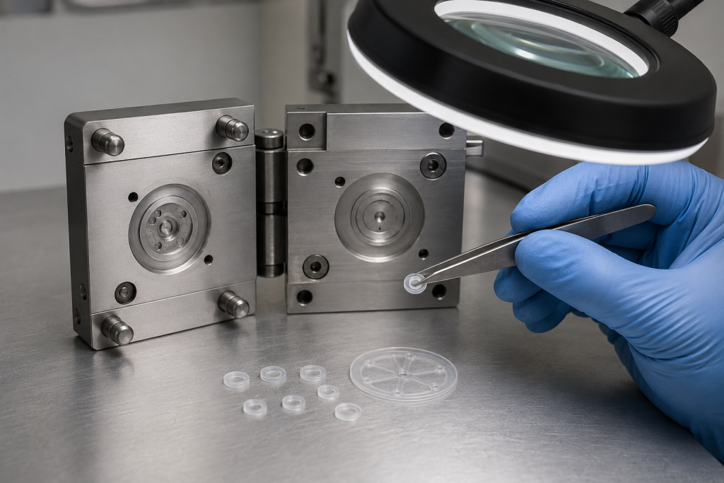
What Is LSR Micro Molding?
LSR micro molding generally involves one or more of the following characteristics:
- Very low part or shot weight
- Submillimeter walls or membranes
- Narrow flow channels
- Microscopic holes, slits or sealing features
- Closely spaced ribs, posts and shut-off surfaces
- Tight tolerances on small functional dimensions
- Miniature inserts requiring silicone overmolding
- Multi-cavity production with very small material volumes
Micro molding is defined by manufacturing difficulty rather than a single part-size limit. A relatively large component can still require micro-molding technology if it contains a critical thin membrane, micro-orifice or miniature sealing geometry.
Precision micro-injection equipment can handle extremely small shot volumes and fine structures, but machine repeatability becomes increasingly important as the material quantity decreases. ENGEL describes micro molding applications involving very fine structures and part weights measured in thousandths of a gram.
Why Use LSR for Micro Components?
LSR offers several advantages for miniature molded parts:
- Low-viscosity material can fill small cavities and thin sections.
- Platinum-addition curing supports clean, automated processing.
- Flexible parts can sometimes be demolded from shapes that would trap rigid plastics.
- A broad hardness range is available.
- Suitable formulations can provide heat, chemical and environmental resistance.
- LSR can be overmolded onto metal or compatible plastic inserts.
- Cold-runner systems can reduce material waste.
Standard LSR is normally supplied as two components that are precisely metered and mixed before injection. Dow, for example, describes its SILASTIC RBL-9200 series as a 1:1 LSR system with improved flowability and processing performance. Dow SILASTIC RBL-9200-50 product information
The same flowability that helps LSR enter microfeatures also increases the risk of material entering tiny gaps at parting lines and shut-offs. Flash control is therefore one of the most important differences between conventional and micro LSR tooling.
Is There a Universal Minimum Wall Thickness?
There is no universal minimum wall thickness for an LSR component.
The achievable wall depends on the interaction of:
- Wall thickness and flow length
- Material viscosity and hardness
- Gate location and gate size
- Cavity temperature distribution
- Injection speed and pressure
- Vacuum and venting efficiency
- Geometry around the thin section
- Required dimensional tolerance
- Demolding direction
- Tear resistance of the cured material
- Production volume and process-capability requirements
A thin membrane located immediately beside the gate may fill consistently, while the same thickness at the end of a long flow path may short-shot or trap air.
The practical question is therefore not “What is the thinnest wall LSR can mold?” It is:
What wall thickness can this material, geometry and tooling concept produce repeatedly within the required functional tolerance?
Minimum thickness should be confirmed through DFM analysis, mold-flow evaluation when appropriate, prototype inserts and production trials using the intended material formulation.
Designing Thin LSR Walls
Keep the Flow Path Short
Place the gate so material reaches the thinnest critical region before curing significantly advances. Long, narrow flow paths increase the pressure needed to fill the cavity and reduce the available processing window.
If the gate cannot be placed near the thin section, consider:
- Multiple gates
- A different part orientation
- A thicker feed section
- Gradual thickness transitions
- A revised cold-runner layout
Avoid Abrupt Thickness Changes
A sudden transition from a thick section to a thin membrane can create hesitation, trapped air or uneven filling.
Use smooth transitions and appropriate radii where the function permits. A gradual transition also reduces stress concentration during demolding and repeated operation.
Evaluate Demolding, Not Only Filling
A membrane may fill correctly but still tear, stretch or fold during removal.
The design team should check:
- Maximum demolding strain
- Location of undercuts
- Peel direction
- Part adhesion to each mold half
- Robot gripping position
- Ejector or air-ejection locations
- Support available during handling
Increasing membrane thickness slightly can sometimes improve yield more effectively than changing multiple process parameters.
Designing Common Microfeatures
Thin Membranes
Thin membranes are used in diaphragms, pressure sensors, valves and switches. Important variables include membrane thickness, unsupported diameter, edge radius and local stress.
Specify the membrane’s functional requirements—such as opening pressure, displacement, response force or cycle life—in addition to its dimensions.
Microholes and Slits
A small hole or slit may be formed with a mold pin or created through a secondary operation.
Molded openings eliminate secondary processing but introduce several risks:
- Small pins can bend or break.
- LSR may flash around the pin shut-off.
- The feature may deform during demolding.
- Measuring the true opening can be difficult.
- Minor flash can significantly change flow performance.
For valve slits or calibrated orifices, functional flow testing may provide more useful acceptance data than dimensional inspection alone.
Narrow Channels
Microchannels require careful venting because displaced air has little space to escape. Dead-end channels are especially sensitive to trapped air.
Vent the end of the flow path and avoid unnecessary sharp corners. If the channel carries a fluid or gas, validate both channel dimensions and actual pressure-drop or flow-rate performance.
Ribs and Posts
Very small ribs and posts can improve stiffness, positioning or sealing, but tall slender features may deform during molding or demolding.
Useful design practices include:
- Supporting tall features where possible
- Providing adequate root radii
- Avoiding unnecessarily sharp tips
- Maintaining enough spacing for tool manufacture and cleaning
- Using replaceable mold inserts for fragile or wear-sensitive details
Micro Sealing Beads
A miniature sealing bead must be designed together with the mating component. Bead height alone does not determine sealing performance.
Also evaluate:
- Compression percentage
- Bead width
- Mating-surface finish
- Assembly tolerance
- Compression stop
- Dureza del material
- Deformación permanente por compresión a largo plazo
- Fluid, temperature and pressure exposure
Mold Design for LSR Micro Molding
Precision Cavity Inserts
Microfeatures are often machined into removable cavity inserts. Replaceable inserts make it easier to:
- Modify a critical dimension
- Repair damaged microfeatures
- test alternative geometries
- Maintain the mold without replacing the complete cavity block
Machining capability should be reviewed before finalizing extremely small radii, deep slots or high-aspect-ratio features.
Cold-Runner and Gate Design
A cold-runner system keeps the LSR below curing temperature until it enters the heated cavity. Direct gating can reduce sprue waste and secondary trimming, while indirect gating can simplify tooling but creates a runner or gate that must be removed.
El WACKER LSR processing guideline notes that direct cold-runner gating can eliminate sprue waste and finishing operations, although the most suitable system depends on mold complexity and production requirements.
For a micro component, the gate should:
- Deliver a repeatable material volume
- Fill critical thin sections early
- Avoid damaging a functional surface
- Produce an acceptable vestige
- Avoid a fragile location
- Remain thermally stable over long production runs
Vacuum and Venting
Air occupying a microcavity must escape before the advancing LSR seals the venting path.
A complete LSR production cell can include metering, injection, vacuum, mold heating and cooling, robotic handling and process-data monitoring. Sumitomo (SHI) Demag highlights these integrated controls for stable LSR production.
Vent locations should be selected according to the predicted end-of-fill regions. Vent dimensions must allow air to leave without allowing unacceptable silicone flash.
Thermal Balance
The mold must cure the part uniformly without causing the material to cure prematurely near the gate.
Inconsistent cavity temperatures can produce:
- Short shots
- Uneven cure
- Dimensional variation
- Difficult demolding
- Irregular flash
- Cavity-to-cavity differences
Thermal balance is especially important in multi-cavity micro molds because small parts respond quickly to local temperature variation.
Flash Control in Micro LSR Parts
Flash is silicone that escapes through a gap between mold surfaces. On a conventional component, a small amount of flash may be cosmetic. On a micro valve, channel or sealing surface, the same flash can block flow or cause leakage.
Typical Causes of Flash
| Posible causa | Effect | Corrective direction |
|---|---|---|
| Insufficient clamping force | Mold surfaces separate during filling | Verify projected area, clamping force and mold support |
| Excessive holding pressure or time | LSR is forced into shut-off gaps | Reduce and optimize the holding stage |
| Parting-line mismatch | Localized flash around the cavity | Inspect mold alignment and insert seating |
| Damaged or contaminated shut-off | Repeatable flash at one location | Clean, repair or replace the affected insert |
| Excessive injection speed | Pressure spike or unstable filling | Use a controlled or staged injection profile |
| Poor venting | Trapped air requires higher filling pressure | Improve vacuum and end-of-fill venting |
| Uneven mold temperature | Inconsistent viscosity and curing | Check heaters, sensors and thermal balance |
| Insert dimensional variation | Gap forms around an overmolded insert | Control insert dimensions and location |
WACKER’s troubleshooting guidance specifically associates overpacking and flash with insufficient clamping force and excessive holding pressure or holding time. It also links air inclusions to inadequate deaeration, insufficient vacuum and unsuitable injection speed. WACKER processing guideline
Define Flash Requirements by Functional Zone
“Flash-free” should not be the only drawing statement. Divide the part into inspection zones:
- Critical sealing surfaces
- Flow paths and orifices
- Assembly interfaces
- Patient- or skin-contact surfaces
- Cosmetic surfaces
- Nonfunctional hidden regions
Specify the permitted flash height, width or presence for each relevant zone. A visual reference sample can help align expectations between engineering, production and quality teams.
Dimensional Tolerances and Inspection
Miniature silicone components are soft, flexible and easily deformed during measurement. A conventional contact gauge can compress the part and report a dimension smaller than its free-state thickness.
ASTM D3767 explains that the pressure applied by a measurement instrument can significantly affect thickness readings on soft rubber products. Therefore, the instrument type, contact force, anvil geometry, conditioning and measurement procedure should be defined. ASTM D3767-03(2020)
Possible inspection methods include:
- Optical vision measurement
- Toolmaker’s microscope
- Non-contact profilometry
- White-light or confocal measurement
- Low-force thickness gauge
- Micro-CT for inaccessible internal geometry
- Calibrated go/no-go fixtures
- Automated camera inspection
- Functional flow or leak testing
ISO 3302-1 provides dimensional tolerance classes and test methods for molded rubber products, but a micro LSR component may require project-specific tolerances and capability studies beyond a general tolerance class. ISO 3302-1:2014
Measurement-system analysis should be completed before using capability indices such as Cp or Cpk. Otherwise, measurement variation may be incorrectly interpreted as process variation.
Material Selection
Do not select an LSR grade using hardness alone. Review:
- Mixed-material viscosity
- Flow behavior
- Resistencia al desgarro
- Alargamiento
- Resistencia a la tracción
- Deformación permanente por compresión
- Cure characteristics
- Resistencia a la temperatura
- Compatibilidad química
- Regulatory or biocompatibility requirements
- Pigment and additive package
- Post-curing requirements
The actual production formulation should be used for validation. Pigment, additives and material-lot variation can affect flow, cure behavior and the appearance of small defects.
Contamination control is also important because platinum-cured LSR can be inhibited by materials containing substances such as sulfur or certain amines. Tool-cleaning products, gloves, insert coatings and nearby molding materials should therefore be reviewed for compatibility.
Process Validation
A robust validation plan should include more than a few visually acceptable samples.
1. DFM Review
Confirm:
- Minimum local wall thickness
- Flow length
- Gate position
- Venting locations
- Parting-line and shut-off strategy
- Método de desmoldeo
- Critical-to-function dimensions
- Inspection access
2. Tool Trials
Record the relationship between:
- Injection speed
- Presión de inyección
- Holding pressure and time
- Temperatura del molde
- Nivel de vacío
- Tiempo de curado
- Part weight
- Flash condition
- Critical dimensions
3. Multi-Cavity Evaluation
Measure parts by cavity rather than combining all results. An overall average may hide a runner-balance or thermal problem affecting one cavity.
4. Pilot Production
Run enough consecutive cycles to identify:
- Startup variation
- Thermal drift
- Material-lot effects
- Mold contamination
- Vent blockage
- Progressive flash
- Demolding damage
- Robot-handling consistency
5. Functional Validation
Depending on the component, testing may include:
- Air or liquid leakage
- Crack pressure
- Caudal
- Burst pressure
- Compression force
- Actuation force
- Pull-out force
- Repeated cycling
- Envejecimiento térmico
- Chemical exposure
- Exposición a la esterilización
Common LSR Micro-Molding Defects
| Defecto | Likely contributors |
| Tiro corto | Long thin flow path, insufficient venting, low material volume, premature curing |
| Flash | Shut-off gap, excessive pressure, insufficient clamp force, mold damage |
| Air trap or burn mark | Poor vacuum, blocked vent, unsuitable injection speed |
| Torn membrane | Excessive demolding strain, insufficient tear strength, sharp transition |
| Distorted microfeature | Early ejection, poor support, handling damage |
| Gate damage | Gate placed in a fragile region or unsuitable degating method |
| Cavity-to-cavity variation | Unbalanced runner, temperature variation, inconsistent venting |
| Incomplete cure | Insufficient mold temperature or cure time, cure inhibition |
| Inestabilidad dimensional | Measurement compression, process variation, post-cure or conditioning effects |
Cost Drivers
The principal cost drivers are usually:
- Number and complexity of microfeatures
- Required mold precision
- Number of cavities
- Cold-runner and valve-gate configuration
- Vacuum requirements
- Replaceable micro inserts
- Inspection time
- Automated demolding and handling
- Flash acceptance criteria
- Validation and traceability requirements
- Expected production volume
Extremely tight tolerances should be assigned only to dimensions that influence performance. Unnecessary tolerances can substantially increase tooling, inspection and maintenance costs without improving the product.
RFQ Checklist for an LSR Micro-Molded Component
Provide the following information when requesting a quotation:
- 2D drawing and 3D model
- Material grade or required properties
- Silicone hardness and color
- Annual and lifetime volume
- Dimensiones críticas y tolerancias
- Minimum wall or membrane thickness
- Permitted flash by functional area
- Gate and parting-line restrictions
- Surface-finish requirements
- Mating-component information
- Operating temperature and pressure
- Chemical or fluid exposure
- Requisitos normativos
- Leak, flow or force specifications
- Required inspection reports
- Packaging and cleanliness requirements
- Pilot-production quantity
When exact tolerances are not yet known, provide the functional requirement. The molding supplier can then recommend dimensions and controls that are realistic for production.
Preguntas frecuentes
What is the minimum wall thickness for LSR micro molding?
There is no single minimum applicable to every component. Wall thickness must be evaluated together with flow length, material viscosity, gate position, venting, mold temperature, tolerance and demolding requirements.
Can LSR mold microholes and narrow channels?
Yes, but pin strength, shut-off accuracy, venting, flash and inspection must be considered. Functional flow testing may be necessary for very small openings.
Can an LSR micro part be completely flash-free?
Direct gating and precision shut-offs can minimize flash, but the acceptable limit should be defined by location and function. Critical flow and sealing areas normally require more stringent control than hidden nonfunctional regions.
Why is a thin LSR wall difficult to measure?
Silicone deforms under contact pressure. The drawing and inspection plan should specify the measurement method, contact force, fixture and conditioning procedure.
Should a micro LSR part be post-cured?
It depends on the material, application and regulatory requirements. Some medical, food-contact or high-performance applications may require post-curing. Confirm this with the material supplier and molding manufacturer.
Is a prototype mold recommended?
A prototype insert or single-cavity pilot tool is valuable when the design contains an unproven membrane, microchannel, valve slit or extremely tight functional tolerance.
Conclusión
Reliable LSR micro molding depends on more than the nominal minimum wall thickness. The most successful designs balance material flow, feature geometry, gate and vent placement, mold accuracy, flash control, demolding and inspection capability.
Early collaboration with an experienced LSR molding supplier can identify high-risk features before production tooling begins. Send your 3D model, drawing, material requirements, expected volume and critical functional specifications for a detailed DFM and tooling evaluation.
 English
  Japanese
  Korean
  German
  French
  Italian
  Spanish
  Dutch
Dutch  Chinese
  Portuguese
  Polish
  Czech
Czech  Hungarian
  Swedish
  Finnish
  Vietnamese
  Thai
Thai  Turkish
  Arabic
  Russian