
Silicone encapsulation protects sensors and their electronic connections from moisture, dust, vibration, impact, chemicals and temperature cycling. It is used in automotive sensors, outdoor electronics, industrial transmitters, medical devices, battery systems, appliances and IoT equipment.
However, covering a sensor with silicone does not automatically make it waterproof. The encapsulant must bond to the housing, circuit board, wires and inserts without damaging sensitive components or blocking the sensing function.
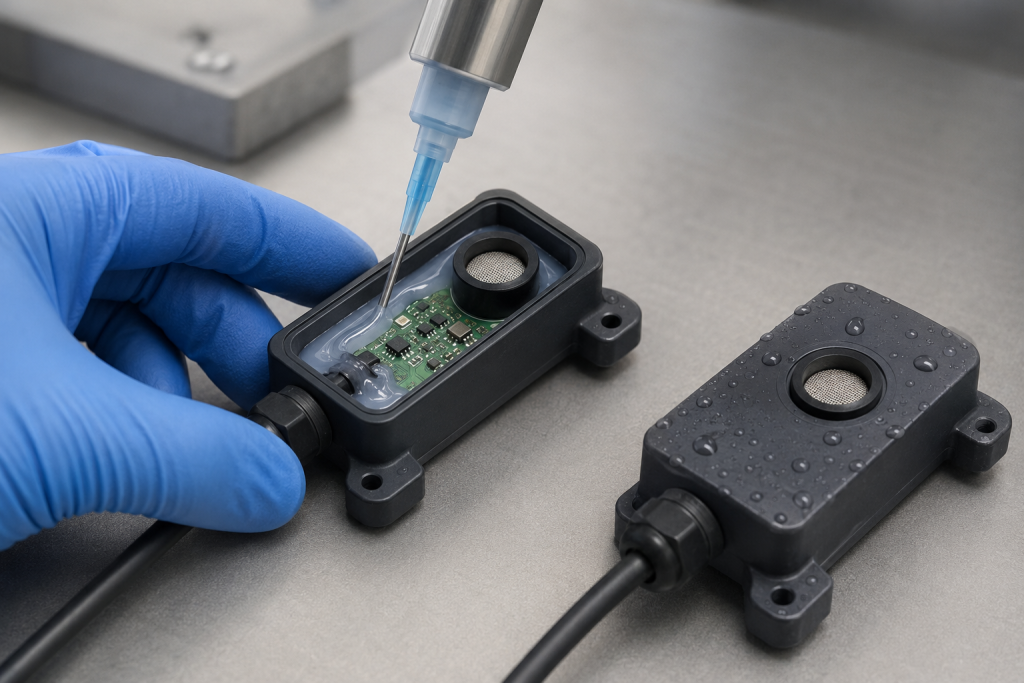
Reliable sensor encapsulation requires engineers to coordinate:
- Sensor operating principle
- Silicone hardness and modulus
- Viscosity and flow
- Cure chemistry
- Electrical and thermal properties
- Adhesion to each substrate
- Encapsulation thickness
- Wire and connector exits
- Mechanical strain relief
- Environmental exposure
- IP testing of the complete assembly
What Is Silicone Sensor Encapsulation?
The term “encapsulation” can describe several different manufacturing methods.
Silicone Potting
A liquid silicone compound is dispensed into a housing and cured around the circuit board and components.
Potting is suitable for:
- Filling irregular spaces
- Protecting electronic assemblies
- Reducing vibration
- Insulating exposed conductors
- Sealing internal cavities
Silicone Gel Encapsulation
A very soft silicone gel surrounds fragile electronic components while applying minimal stress.
Gels are useful for:
- MEMS devices
- Delicate wire bonds
- Power modules
- Pressure-sensitive electronics
- Components exposed to thermal expansion
Dow, for example, describes DOWSIL EG-4175 as a self-priming, addition-curing silicone gel for electronic modules, industrial sensors and actuators. DOWSIL EG-4175 Silicone Gel
القولبة الفوقية بالسيليكون
Liquid silicone rubber is injection-molded around a sensor, housing or insert.
Overmolding can create:
- Controlled external geometry
- Integrated seals
- Cable strain relief
- Mounting features
- A clean finished surface
The sensor and electronics must tolerate the molding pressure and cure temperature.
Conformal Coating
A thin silicone layer is applied to the circuit board surface. It protects against humidity and contamination but does not provide the same mechanical support or complete void filling as potting.
Molded Silicone Boot or Cover
A separate silicone component is assembled over the sensor. This approach allows replacement and rework but requires a reliable mechanical sealing interface.
Start With the Sensor Function
Before selecting a material, determine what the sensor must detect.
A sensor may need direct exposure to:
- Air pressure
- Liquid pressure
- Humidity
- Gas
- Light
- Sound
- Magnetic fields
- Heat
- Mechanical strain
Encapsulating the active area can reduce sensitivity, delay response or completely prevent operation.
The design should divide the assembly into:
- Areas that must be fully encapsulated
- Areas that require a thin controlled membrane
- Areas that require an optical or acoustic window
- Areas that must remain open
- Areas that require venting
- Electrical and mechanical interfaces
Pressure Sensors
A pressure sensor may require a port or flexible diaphragm that transfers pressure to the sensing element.
Important design factors include:
- Membrane thickness
- Membrane diameter
- Silicone modulus
- Temperature-dependent stiffness
- Trapped air volume
- Pressure range
- Response time
- Zero-point drift
A thick or hard silicone layer can change the pressure transfer and introduce calibration error.
Temperature Sensors
Silicone can protect a temperature sensor, but the encapsulation thickness and thermal conductivity affect response time.
A thicker encapsulation may improve mechanical protection while slowing the sensor’s thermal response.
Validate:
- Time to reach target temperature
- Temperature-measurement error
- الدورات الحرارية
- Self-heating
- Heat transfer through the housing
Optical Sensors
Optical sensors may require transparent silicone.
Review:
- Optical transmission at the operating wavelength
- Refractive index
- Haze
- Yellowing
- Bubbles
- تشطيب السطح
- Cure by-products
- UV exposure
- Adhesion to the lens or window
A material that appears visually clear may not have suitable transmission at ultraviolet or infrared wavelengths.
Humidity and Gas Sensors
Humidity and gas sensors normally require controlled exposure to the surrounding atmosphere.
Possible solutions include:
- Selectively encapsulating only the electronics
- Leaving the sensing element exposed
- Using a protective porous membrane
- Creating a dedicated vent channel
- Separating the sensing chamber from the electronics chamber
The environmental barrier must not block the molecules the sensor is intended to detect.
Acoustic and Ultrasonic Sensors
Silicone changes acoustic impedance and damping. Encapsulation may shift resonance, reduce amplitude or change the directional response.
Test the complete assembly across the intended frequency range.
Selecting a Silicone Encapsulant
The material should be selected according to electrical, mechanical, thermal and environmental requirements.
Viscosity and Flow
Low-viscosity materials flow into narrow gaps and around small components.
Potential advantages include:
- Better void filling
- Easier dispensing
- Reduced trapped air
- Improved coverage under components
Possible disadvantages include:
- Leakage through housing gaps
- Flow into sensing ports
- Migration onto contacts
- Difficulty maintaining a controlled thickness
Higher-viscosity materials remain in place more easily but may trap air around components or fail to fill narrow spaces.
Hardness and Modulus
A low-modulus material reduces stress on solder joints, ceramic components, wire bonds and sensitive MEMS structures.
A harder elastomer provides:
- Greater impact resistance
- Better shape retention
- Improved abrasion resistance
- More mechanical support
However, excessive stiffness can transfer housing movement and thermal-expansion stress into the sensor.
DOWSIL EE-3200 is an example of a soft, low-stress encapsulant designed to fill small gaps while reducing internal stress in electronic assemblies. DOWSIL EE-3200 Low Stress Silicone Encapsulant
Do not select material using Shore hardness alone. Review the complete stress-strain behavior and test the finished encapsulated sensor.
Cure Chemistry
Common silicone systems include:
- Addition-cure silicone
- Condensation-cure silicone
- One-part moisture-cure silicone
- Two-part room-temperature cure silicone
- Heat-accelerated silicone
- Moldable LSR
The cure system affects:
- Working time
- Cure speed
- Cure temperature
- By-product generation
- Adhesion
- Equipment requirements
- Cure inhibition risk
- Production throughput
Addition-Cure Silicone
Addition-cure systems can provide clean curing and stable properties, but certain contaminants can inhibit the cure.
Potential compatibility concerns include:
- Sulfur-containing materials
- Some amines
- Certain adhesives
- Some flux residues
- Tin-cured silicone contamination
- Unapproved gloves or cleaning agents
Complete a cure-compatibility test with every production substrate and process chemical.
Condensation-Cure Silicone
Condensation-cure materials may be convenient for room-temperature processing but can release cure by-products. Thick sections and confined geometries may cure differently from thin exposed layers.
Confirm:
- Cure depth
- By-product compatibility
- Corrosion risk
- Venting
- Final electrical performance
Heat Cure
Heat can shorten the manufacturing cycle but may damage batteries, magnets, plastics, adhesives, calibration elements or moisture-sensitive components.
The sensor should be qualified for the complete time-temperature profile.
Mix Ratio and Degassing
Two-part materials require accurate metering and thorough mixing.
Mixing errors may cause:
- Incomplete cure
- Soft or sticky regions
- Property variation
- Poor adhesion
- Electrical contamination
- Reduced production yield
Vacuum degassing or controlled static mixing can reduce trapped air. However, the process should avoid excessive vacuum that causes volatile components or trapped fluids to expand unexpectedly.
Thermal Conductivity
Standard silicone is not necessarily an efficient thermal conductor. Filled formulations can improve heat transfer but may have:
- Higher viscosity
- Greater hardness
- Increased density
- Reduced transparency
- More filler settling
- Different adhesion behavior
Thermally conductive encapsulation is useful when the sensor electronics generate heat or require thermal coupling to a housing.
It may be undesirable when the sensing element needs thermal isolation.
Electrical Properties
For electronic sensors, review:
- Dielectric strength
- Volume resistivity
- Dielectric constant
- Dissipation factor
- Ionic contamination
- Arc resistance
- Tracking resistance
- Flame rating
Typical datasheet values are measured under specific specimen and environmental conditions. Verify the required electrical properties after cure, humidity exposure and thermal aging.
Cure Shrinkage and Thermal Expansion
Even low-shrinkage materials can generate stress when bonded across components with different thermal-expansion rates.
Common substrate combinations include:
- السيليكون
- Aluminum
- Stainless steel
- Copper
- Ceramic
- Glass
- FR-4
- PBT
- PA
- PC
- ABS
- Epoxy
Stress can concentrate at:
- Sharp component corners
- Thick-to-thin transitions
- Cable exits
- Insert edges
- Housing walls
- Sensor diaphragms
Use a low-modulus material, smooth geometry and controlled encapsulation thickness to reduce stress.
Adhesion Requirements
Adhesion can prevent water from traveling along the boundary between silicone and the housing.
The required substrates may include:
- Metal housing
- Plastic housing
- PCB solder mask
- Glass
- Ceramic
- Wire insulation
- Connector inserts
- Optical windows
One silicone formulation may bond well to one substrate and poorly to another.
Surface Cleanliness
Contamination is one of the most common causes of adhesion failure.
Possible contaminants include:
- Mold-release agents
- Machining oil
- Fingerprints
- الغبار
- Plasticizer
- Flux residue
- Silicone oil
- بقايا مواد التنظيف
- الرطوبة
- Oxide layers
The production cleaning process should be documented and controlled.
A surface that looks clean may still contain a film that prevents bonding.
تحضير السطح
Depending on the substrate, preparation may include:
- Solvent cleaning
- Aqueous cleaning
- Plasma treatment
- Corona treatment
- Controlled abrasion
- Primer application
- Preheating
- Drying
Surface treatment has a limited useful lifetime. Parts should be encapsulated within the validated processing window after treatment.
Primers
A primer may improve bonding between silicone and a difficult plastic, metal or glass surface.
The process must control:
- Primer type
- Application thickness
- Coverage
- Drying time
- Contamination
- Shelf life
- Storage
- Cure temperature
Excess primer can migrate into electrical or optical areas, while insufficient coverage can create localized delamination.
Self-Adhesive Silicone
Some silicone formulations are designed to bond without a separate primer.
Self-adhesion can simplify production, but it still depends on:
- Substrate chemistry
- Surface cleanliness
- Cure conditions
- Contact pressure
- Encapsulation thickness
- Aging environment
Validate adhesion on production substrates rather than generic sample plaques.
Mechanical Locking
Adhesion should not always carry the complete mechanical load.
Mechanical retention features can include:
- Undercuts
- Through-holes
- Grooves
- Ribs
- Flanges
- Perforated inserts
- Encapsulated anchors
Mechanical locking is especially useful around cable exits and inserts exposed to pulling or vibration.
Adhesion-Test Methods
ASTM D429 covers several methods for measuring static adhesion between rubber and rigid substrates, primarily metals. It can provide comparative development and production-control data when suitable specimens can be prepared. ASTM D429-14(2023)
For a sensor project, define an application-specific test coupon that reproduces:
- Production substrate
- تشطيب السطح
- التنظيف
- Primer
- Silicone thickness
- Cure process
- Aging exposure
Record both bond strength and failure mode.
Adhesive Failure
The silicone separates cleanly from the substrate. This usually indicates an interface or surface-preparation problem.
Cohesive Failure
The silicone tears while material remains bonded to the substrate. This indicates the interface is stronger than the local silicone.
Substrate Failure
The plastic, coating or other substrate fails before the silicone bond.
Failure mode can provide more useful development information than peak force alone.
Encapsulation Geometry
Controlled Thickness
Avoid large uncontrolled thickness differences. Thick areas can:
- Cure differently
- Trap heat
- Increase material cost
- Generate thermal stress
- Trap bubbles
Very thin areas may fail to cover components or provide sufficient dielectric protection.
Smooth Transitions
Use radii and gradual thickness transitions around:
- PCB edges
- Inserts
- Cable exits
- Housing corners
- Sensor windows
- Mounting features
Sharp corners can trap air and concentrate stress.
Air-Escape Paths
The filling direction should push air toward controlled vents rather than trapping it under components.
Consider:
- Dispense location
- Housing orientation
- Fill speed
- Vacuum assistance
- Component spacing
- Vent position
- Overflow reservoir
Overflow and Expansion Space
Provide controlled space for material-volume variation and thermal expansion. Uncontrolled overflow can contaminate connectors, sensing surfaces or mounting features.
Cable and Wire Exits
Wire exits are frequent leak and fatigue locations.
The design should include:
- Controlled silicone-to-jacket contact
- Mechanical strain relief
- Smooth bend radius
- Wire-positioning fixture
- Adequate encapsulation length
- Compatible wire insulation
- Pull-force validation
Water can travel along individual conductor strands or between the wire jacket and encapsulant. The complete cable construction must therefore be evaluated.
Connector and Pin Interfaces
Avoid allowing silicone to flow onto:
- Electrical contacts
- Mating surfaces
- Locking features
- Test points
- Calibration ports
Use shut-offs, masks, removable plugs or dedicated barriers.
Adhesion Versus Compression Sealing
A bonded silicone interface can prevent leakage, but production variability and aging may cause local delamination.
Where possible, combine adhesion with:
- Radial compression
- An axial sealing bead
- Mechanical locking
- A labyrinth path
- Housing retention
A redundant sealing strategy is more robust than relying on a flat bonded boundary alone.
IP Protection Testing
IEC 60529 classifies the protection provided by electrical enclosures against access, solid foreign objects and water. IEC 60529 consolidated version
An encapsulant does not receive an IP rating by itself. The rating applies to the complete tested assembly, including:
- Sensor housing
- Silicone encapsulation
- Cable
- Connector
- Vent
- Membrane
- Lens
- Mounting interface
- Housing joints
A waterproof silicone compound cannot compensate for an unsealed connector or open sensing port.
Automotive IP Requirements
For sensors used in road vehicles, ISO 20653 specifies IP-code protection and confirmation tests for automotive electrical-equipment enclosures. ISO 20653:2023
Confirm which standard, severity and mounting condition the customer requires before designing the encapsulation.
Common Sensor Leakage Paths
| Leakage path | Possible cause |
|---|---|
| Silicone-to-housing interface | Contamination, low adhesion or thermal stress |
| Wire exit | Jacket incompatibility, movement or insufficient encapsulation length |
| Connector interface | Incomplete mating or damaged seal |
| Around metal pins | Poor wetting or thermal-expansion mismatch |
| Mold parting line | Flash, mismatch or incomplete filling |
| Internal void | Trapped air connected to the exterior |
| Sensor membrane | Tear, excessive thickness or poor bonding |
| Optical window | Adhesion failure or surface contamination |
| Vent path | Incorrect membrane or uncontrolled opening |
| Housing crack | Overmolding pressure or thermal stress |
Leak-Test Methods
Pressure-Decay Testing
The encapsulated sensor is pressurized, isolated and monitored for pressure loss.
Define:
- Test pressure
- Stabilization time
- Internal volume
- Test duration
- Temperature
- Maximum permitted decay
- Fixture leakage
Vacuum-Decay Testing
A vacuum is applied and the pressure change is monitored after isolation.
The deformation direction may differ from a positive-pressure test, so select the method according to actual service.
Bubble-Immersion Testing
A pressurized assembly is submerged and inspected for bubbles.
This method helps locate leaks but should use controlled pressure, immersion depth and observation time.
Tracer-Gas Testing
Tracer-gas methods can detect smaller leak paths than water immersion. The acceptance limit must be correlated with actual service requirements.
Functional Water-Ingress Testing
Complete the required spray, jet or immersion test while the sensor is mounted in its intended orientation.
After testing, verify both internal dryness and sensor function.
Environmental Preconditioning
A newly encapsulated sensor may pass an IP test but fail after aging.
Repeat sealing tests after relevant environmental exposure.
Temperature Change
IEC 60068-2-14 provides temperature-change tests for evaluating the effects of specified ambient-temperature transitions on components and equipment. IEC 60068-2-14:2023
Thermal cycling can reveal:
- Adhesion loss
- Housing cracks
- Wire-interface leakage
- Calibration drift
- Encapsulant separation
Damp Heat
IEC 60068-2-78:2025 defines steady-state damp-heat testing to investigate the effect of high humidity at constant temperature. IEC 60068-2-78:2025
Humidity testing should include electrical and functional measurements, not only visual inspection.
الاهتزاز
IEC 60068-2-6 provides a sinusoidal-vibration test method for identifying mechanical weakness and performance degradation in components and equipment. IEC 60068-2-6:2007
Vibration can cause:
- Wire fatigue
- Delamination
- Connector movement
- Cracking around rigid inserts
- Damage to internal solder joints
Chemical Exposure
Depending on the application, expose the assembly to:
- Oils
- Fuels
- Coolants
- Cleaning agents
- Detergents
- Salt water
- Disinfectants
- Sweat
- Process chemicals
Measure changes in hardness, volume, adhesion, leakage and sensor performance.
Sensor Calibration After Encapsulation
Encapsulation can change the sensor response even when no leakage occurs.
Verify:
- Zero offset
- Sensitivity
- Linearity
- Hysteresis
- Response time
- Temperature compensation
- Noise
- Drift
Calibration should be checked:
- Before encapsulation
- After cure
- After post-cure
- After thermal cycling
- After humidity exposure
- After vibration
- After IP testing
Overmolding Process Risks
LSR overmolding offers precise external geometry but exposes the sensor to:
- Injection pressure
- Mold clamping
- Elevated temperature
- Vacuum
- Insert positioning
- Silicone flow
- Cure chemistry
Fragile sensors may require:
- Lower-pressure processing
- Protective insert carriers
- Reduced mold temperature
- Controlled cavity support
- Staged encapsulation
- Potting instead of injection molding
Insert Positioning
Sensors, PCBs and wires must remain in position during material filling.
Use:
- Mechanical nests
- Datum features
- Removable supports
- Wire-routing channels
- Locating pins
- Automated vision verification
Poor insert positioning can create thin encapsulation, blocked ports or exposed conductors.
Manufacturing Process Control
A controlled encapsulation process should monitor:
- Material lot
- Storage condition
- Mix ratio
- Mixing quality
- Dispense weight
- Vacuum degassing
- Fill time
- Working time
- Mold or housing temperature
- Cure time
- Post-cure
- Primer application
- Surface-treatment time
- Part cleanliness
Void Inspection
Voids can reduce dielectric protection, create moisture paths or concentrate stress.
Inspection methods include:
- Visual inspection for transparent materials
- X-ray
- Industrial CT
- Ultrasound
- Sectioning
- Weight comparison
- Electrical testing
- Leak testing
Not every internal bubble causes failure, but acceptance limits should be based on location, size and function.
Production Inspection
Possible controls include:
- Encapsulant weight
- Fill height
- Surface coverage
- Wire position
- Shore hardness on reference specimens
- Cure verification
- Adhesion coupons
- Pressure-decay testing
- Electrical insulation testing
- Functional sensor test
- Vision inspection
For high-volume production, automated leak and functional testing can identify process drift earlier than destructive inspection.
Common Encapsulation Failures
| Failure | Likely cause | Corrective direction |
| Silicone remains sticky | Mix error or cure inhibition | Review material handling and contamination |
| Bubbles around components | Poor degassing or trapped-air geometry | Change fill direction and vacuum process |
| Delamination from housing | Contamination or incompatible surface | Improve cleaning, treatment or primer |
| Sensor reading shifts | Encapsulant too stiff or thick | Reduce modulus or revise active-area geometry |
| Water travels along cable | Poor jacket adhesion or cable movement | Add mechanical sealing and strain relief |
| Housing cracks after cycling | Thermal-expansion stress | Use lower modulus and smoother transitions |
| Connector is contaminated | Uncontrolled silicone flow | Improve shut-off, masking and dispense control |
| Voids under PCB | High viscosity or rapid filling | Reduce viscosity or use vacuum-assisted filling |
| Optical output decreases | Haze, bubbles or yellowing | Select optical-grade material and control cure |
| Seal passes initially but fails after aging | Adhesion loss or compression set | Add environmental preconditioning and redesign |
| Insert moves during molding | Inadequate fixture | Improve insert location and cavity support |
| Local overheating | Low thermal conductivity or excessive thickness | Review thermal path and encapsulant selection |
Validation Plan
1. Define Sensor Function
Identify areas that must remain exposed, flexible, transparent or vented.
2. Select Candidate Materials
Compare:
- Cure system
- Viscosity
- الصلابة
- Modulus
- Adhesion
- Thermal conductivity
- Dielectric properties
- Temperature range
- Fluid compatibility
- Regulatory requirements
3. Conduct Compatibility Testing
Test cure and adhesion on all production substrates, coatings, wires, adhesives and cleaning residues.
4. Build Prototype Assemblies
Use production-representative:
- Housings
- PCBs
- Cables
- Connectors
- Surface treatments
- Dispensing or molding process
5. Complete Initial Testing
Measure:
- Adhesion
- التسرب
- Electrical insulation
- Sensor calibration
- Pull strength
- Visual quality
6. Environmental Conditioning
Complete required thermal, humidity, vibration and chemical tests.
7. Repeat IP and Functional Tests
Evaluate leakage, adhesion and sensor calibration after every critical exposure.
8. Pilot Production
Track variation by:
- Material lot
- Mold cavity
- Dispensing head
- Operator
- Housing lot
- Sensor lot
RFQ Checklist
Provide the following information when requesting a custom silicone sensor-encapsulation quotation:
- Sensor type and operating principle
- 2D drawing and 3D model
- Areas that must remain exposed
- Housing and substrate materials
- PCB coating and solder mask
- Wire and cable materials
- Operating-temperature range
- Target IP code
- Pressure or immersion requirement
- Chemical exposure
- Required hardness or modulus
- Thermal-conductivity requirement
- Optical-transmission requirement
- Dielectric requirement
- Adhesion requirement
- Pull-force requirement
- Cure-temperature limit
- Maximum injection pressure
- Calibration tolerance
- Flammability requirement
- Regulatory requirements
- Annual production volume
- Inspection and traceability requirements
If the encapsulation method has not been selected, provide the complete sensor assembly and environmental requirements. The supplier can then compare potting, gel encapsulation, overmolding and separate molded-cover options.
الأسئلة الشائعة
Does silicone encapsulation make a sensor waterproof?
Not automatically. Waterproof performance depends on adhesion, housing geometry, cable exits, connectors, vents and the complete assembly process.
Is softer silicone always better for sensors?
Soft silicone reduces mechanical stress but may provide less abrasion resistance or shape control. The correct modulus depends on the sensor and environment.
Can silicone cover a pressure-sensor diaphragm?
Yes, but membrane thickness and modulus can change sensitivity, response time and calibration. Prototype testing is essential.
Why does silicone separate from plastic?
Possible causes include mold release, low surface energy, contamination, unsuitable primer, inadequate cure or thermal-expansion stress.
Is primer always required?
No. Some self-adhesive silicone grades bond without primer, while other substrate combinations need plasma treatment or primer. Production substrates must be tested.
What is the difference between potting and overmolding?
Potting fills a housing with liquid material, generally at relatively low pressure. Overmolding forms an external silicone shape around the sensor inside a mold.
Does IP67 apply to the silicone material?
No. The IP rating applies to the complete tested sensor assembly, including its housing, wires, connectors and openings.
When should IP testing be performed?
Test initial assemblies and repeat the test after relevant thermal cycling, humidity, vibration, chemical exposure and mechanical loading.
How can bubbles be prevented?
Use correct mixing, vacuum degassing, controlled fill speed, suitable housing orientation and designed air-escape paths.
Can an encapsulated sensor be repaired?
Soft gels and some potting materials may be removable, while bonded overmolding is usually difficult to rework. Define serviceability before selecting the encapsulation method.
الخلاصة
Successful silicone sensor encapsulation requires a balance between environmental protection and sensor function. The material must flow around the electronics, bond to multiple substrates and remain flexible enough to accommodate thermal and mechanical movement.
IP performance should be verified on the complete sensor assembly before and after environmental conditioning. Early material screening, adhesion testing and functional prototypes can prevent delamination, leakage and calibration drift during production.
Send your sensor drawing, substrate materials, operating environment, target IP rating and calibration requirements for a silicone encapsulation DFM and material-selection review.
 English
  Japanese
  Korean
  German
  French
  Italian
  Spanish
  Dutch
Dutch  Chinese
  Portuguese
  Polish
  Czech
Czech  Hungarian
  Swedish
  Finnish
  Vietnamese
  Thai
Thai  Turkish
  Arabic
  Russian