
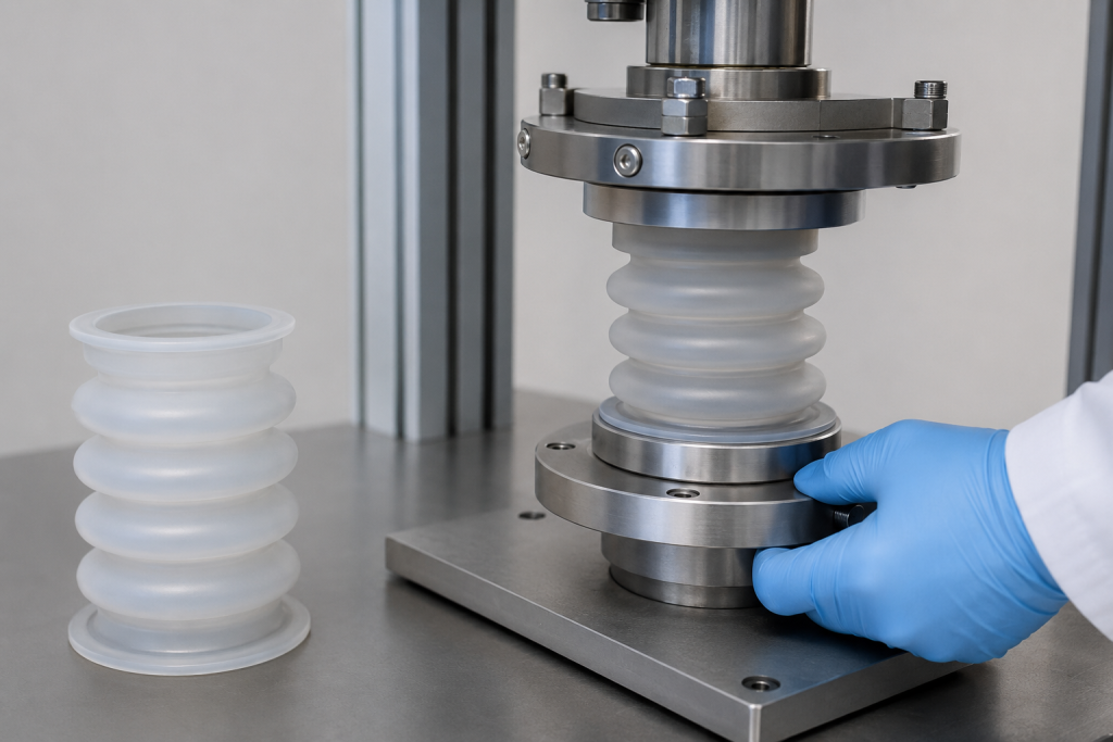
Silicone bellows are flexible molded components used to protect moving shafts, compensate for displacement, isolate sensitive assemblies and contain air or fluids. They are found in medical equipment, sensors, actuators, pumps, automotive systems, electronics and industrial machinery.
A bellows may appear to be a simple series of molded folds, but small changes in wall thickness, convolution geometry or material hardness can substantially affect:
- Available stroke
- Return force
- Spring rate
- Internal stress
- Pressure resistance
- Fatigue life
- أداء العزل
- Moldability and cost
Successful silicone bellows design requires the geometry, material, motion, pressure and operating environment to be evaluated as one system.
What Does a Silicone Bellows Do?
Depending on the application, a bellows may provide one or more functions.
Motion Compensation
The convolutions allow axial, lateral or angular movement between two connected components.
Dust and Contamination Protection
A bellows can protect shafts, joints, sensors and actuators from dust, particles and external contact.
Fluid or Air Containment
A sealed bellows can contain air, gas or liquid while changing volume during operation.
Pressure or Vacuum Response
The bellows may expand, contract or generate force in response to a pressure difference.
Return-Spring Function
The elastomeric folds can create a restoring force without using a separate metal spring.
Vibration Isolation
A flexible bellows can reduce the transfer of small movements between connected components, although it should not automatically be treated as a dedicated vibration isolator.
Define the Motion Before Designing the Bellows
The required motion should be expressed using clear reference dimensions.
Important dimensions include:
- Free length
- Installed length
- Minimum compressed length
- Maximum extended length
- Nominal operating position
- Normal working stroke
- Maximum transient stroke
- Outside diameter
- Inside clearance diameter
- End-connection dimensions
The working stroke is often expressed as:
Total axial stroke = Maximum extended length − Minimum compressed length
However, designing only around the total stroke can hide important strain differences. A bellows operating mostly in extension may behave differently from one cycling equally between compression and extension.
The drawing should therefore identify the neutral or installed position and show how much movement occurs in each direction.
Axial, Lateral and Angular Movement
Axial Movement
Axial compression and extension are the most common bellows motions. The convolutions open and close along the centerline.
Lateral Movement
Lateral offset occurs when the two ends remain approximately parallel but their centerlines move apart.
Angular Movement
Angular motion occurs when one end rotates relative to the other.
Combined Movement
Real assemblies may combine axial stroke, lateral displacement, angular movement, torsion and pressure.
Do not validate these motions independently and assume the results can be added together. Combined movement can concentrate strain in one side of a convolution and significantly reduce fatigue life.
Bellows Geometry
A molded silicone bellows typically includes:
- End cuffs or mounting flanges
- Root radii
- Convolution sidewalls
- Outer crowns
- Valley sections
- Transition areas
- Optional sealing beads or reinforcement features
Each feature influences movement and stress.
Number of Convolutions
Adding convolutions generally distributes the total movement across more folds. This can reduce the movement required from each individual convolution.
Potential advantages include:
- Longer available stroke
- Lower local deformation per fold
- Lower axial stiffness in many designs
- Improved accommodation of misalignment
Possible disadvantages include:
- Increased overall length
- Greater mold complexity
- More potential fatigue locations
- Reduced lateral stability
- Increased risk of buckling
- More difficult cleaning
The number of folds should be selected according to the stroke, available space, pressure and required spring force—not only appearance.
Convolution Depth and Diameter
Deeper convolutions can increase flexibility and stroke, but they also create more unsupported material and can increase sensitivity to:
- الانحناء
- Pressure deformation
- Wall-thickness variation
- Mold filling
- Demolding strain
- Convolution contact
A very shallow bellows may be easier to mold and pressure-resistant but provide insufficient movement.
The inner and outer diameters must also provide clearance for any moving shaft throughout the complete stroke and misalignment range.
سماكة الجدار
Bellows wall thickness is one of the strongest influences on spring rate, pressure capability and fatigue performance.
Thinner Walls
Potential advantages:
- Lower actuation force
- Lower spring rate
- Easier axial movement
- Greater sensitivity in pressure-responsive devices
Possible disadvantages:
- Higher molding variation
- Reduced pressure resistance
- Greater risk of tearing
- Difficult demolding
- Local collapse under vacuum
- Increased sensitivity to flash and surface defects
Thicker Walls
Potential advantages:
- Higher pressure resistance
- Better shape stability
- Easier handling
- Greater resistance to incidental damage
Possible disadvantages:
- Higher actuation force
- Higher spring rate
- Increased internal strain during folding
- Greater heat generation during rapid cycling
- Reduced available compressed length
A nominal wall dimension is not enough. Wall-thickness uniformity around every convolution should be included in the inspection plan.
Root and Crown Radii
Sharp transitions concentrate strain and are common crack-initiation locations.
Use smooth radii at:
- Inner convolution roots
- Outer crowns
- Cuff-to-bellows transitions
- Flange transitions
- Local thickness changes
The radius should be large enough to reduce strain concentration but not so large that adjacent convolutions contact too early.
A thin root next to a heavy end cuff is especially vulnerable because stiffness changes abruptly at the transition.
Convolution Pitch
Pitch is the axial distance between corresponding points on adjacent convolutions.
If the pitch is too small:
- Folds may contact early during compression.
- Spring force may rise sharply near the compressed limit.
- Friction and heat may increase.
- Surfaces may stick together.
If the pitch is too large:
- The bellows may require more installed space.
- Sidewalls may experience greater bending or stretching.
- Lateral stability may decrease.
The compressed position should be reviewed in a section view to confirm that fold contact does not occur during normal operation.
Preventing Convolution Bottoming
When adjacent convolutions touch, the bellows can no longer deform in its intended manner. The force-displacement curve becomes much steeper, and local contact can produce abrasion or heat.
Avoid using full convolution contact as the normal mechanical stop. Instead, provide an external stop in the assembly where practical.
If limited fold contact is unavoidable, include it in the fatigue test and inspect the contact areas for:
- Polishing
- Surface wear
- التمزق
- Heat damage
- Permanent adhesion
Silicone Bellows Spring Rate
Spring rate describes how much force is required to move the bellows through a specified displacement.
For a simple linear spring:
k = ΔF ÷ Δx
Where:
- k is spring rate
- ΔF is the change in force
- Δx is the change in displacement
Silicone bellows usually do not behave as perfectly linear springs. Their force-displacement curve can change throughout the stroke.
For this reason, engineers may specify:
- Secant spring rate over a displacement range
- Tangent spring rate at a particular position
- Force at several defined displacements
- Maximum actuation force
- Return force after unloading
A requirement such as “spring rate: 2 N/mm” is incomplete unless the measurement range, direction and conditioning are defined.
Why the Loading and Unloading Curves Differ
Rubber exhibits hysteresis. Some mechanical energy is dissipated during each cycle, so the force measured during compression may differ from the return force during unloading.
The size of the hysteresis loop depends on:
- Silicone formulation
- الصلابة
- Strain level
- Cycling speed
- Temperature
- Previous cycling
- Aging
- Geometry
For an actuator, switch or dosing system, the unloading curve may be just as important as the loading curve.
Material Hardness and Spring Force
Harder silicone usually increases the force required to deform the same geometry, but hardness alone cannot predict bellows spring rate.
Two materials with the same Shore A hardness may have different:
- Stress-strain behavior
- Modulus
- Hysteresis
- Tear strength
- مجموعة الضغط
- Temperature response
- Fatigue resistance
ASTM D575 provides compression-deflection methods for comparing rubber-material stiffness in compression. However, a material-specimen test does not replace force-displacement testing of the finished bellows because convolution geometry dominates component behavior. ASTM D575-91(2024)
Pressure-Induced Axial Force
If the bellows contains internal pressure or operates against a vacuum, pressure creates an additional axial load.
The pressure contribution can be approximated as:
Pressure force = Pressure difference × Effective area
The effective area may not be identical to the open bore area because the convoluted wall changes the load path.
The assembly force may therefore include:
- Elastomer spring force
- Pressure-induced force
- Friction from guides or seals
- External mechanical load
A bellows tested only at atmospheric pressure may behave differently when installed in a pressurized system.
Internal Pressure
Internal pressure tends to expand the bellows and may increase axial force or distort the convolutions.
Check:
- Maximum continuous pressure
- Peak pressure
- Pressure-cycle frequency
- Temperature at pressure
- Pressure pulsation
- Required burst margin
- End-retention strength
- Leakage requirement
External Pressure and Vacuum
External pressure or internal vacuum can cause the convolutions to collapse inward.
Possible corrective directions include:
- Revised convolution profile
- Reduced unsupported diameter
- Increased wall thickness
- Higher material stiffness
- Internal support rings
- External guides
- Shorter free length
Any reinforcement must be reviewed for wear, bonding and contamination risk.
Buckling and Lateral Stability
A long, soft bellows can buckle before reaching the intended axial stroke. Buckling may be caused by:
- Excessive free length
- High compression
- Offset mounting
- Uneven wall thickness
- Pressure loading
- Insufficient guidance
- Eccentric end fixtures
If the bellows is intended to move only axially, guide the connected shaft or provide external alignment features. The bellows should not be expected to correct major assembly misalignment while maintaining precise spring performance.
End-Cuff and Flange Design
The end connections transfer motion and pressure into the bellows.
Common attachment methods include:
- Clamp grooves
- Barbed fittings
- Compression flanges
- Adhesive bonding
- Overmolding onto plastic or metal
- Retaining rings
- Snap-fit grooves
The end cuffs should be stiff enough to remain attached but transition gradually into the flexible convolution section.
Check:
- Pull-off force
- Clamp pressure
- التسرب
- Rotation
- Cuff tearing
- قوة الالتصاق
- Stress concentration at the first fold
The first convolution beside the cuff is often a critical fatigue location.
Material Selection
Important silicone properties include:
- Shore hardness
- قوة الشد
- الاستطالة
- Tear strength
- مجموعة الضغط
- Modulus
- Hysteresis
- Temperature resistance
- Fluid compatibility
- UV and ozone resistance
- Regulatory compliance
- Post-cure requirements
A grade with high elongation is not automatically the best fatigue material. Crack initiation, tear propagation, filler system and curing quality must also be considered.
Published silicone grades show that hardness, elongation, tear strength and compression set can vary independently. For example, Shin-Etsu lists high-tear LSR grades across several hardness levels with different mechanical and compression-set values. Shin-Etsu high-tear silicone example
Use the intended production formulation—including pigment and additives—for prototype and fatigue testing.
Compression Set and Permanent Deformation
If a bellows remains compressed for long periods, it may not fully return to its original free length.
ASTM D395 evaluates the ability of rubber compounds to retain elastic properties after prolonged compressive stress. The standard also notes that compression-set testing mainly represents static conditions; dynamic deformation is better represented by flexing or hysteresis testing. ASTM D395-18(2025)
For a bellows, monitor:
- Free-length change
- Return-force loss
- Permanent convolution deformation
- Leakage after storage
- Spring-rate change
Static compression-set data are useful for material screening but cannot predict complete bellows fatigue life.
Fatigue-Life Testing
Bellows fatigue results from repeated tensile, compressive, bending and shear strain in the convolutions.
Cracks commonly begin at:
- Inner roots
- Outer crowns
- Cuff transitions
- Parting lines
- Gate vestiges
- Areas with thin walls
- Flash-removal damage
- Mold-surface defects
- Locations where folds contact
Factors Affecting Fatigue Life
Strain Amplitude
Larger movement per cycle generally creates more severe deformation. Reducing the working stroke or adding convolutions may reduce the strain carried by each fold.
Mean Position
A cycle from a slightly compressed condition to neutral may behave differently from a cycle extending the bellows on every stroke.
Frequency
Higher cycling frequency can increase self-heating because of elastomer hysteresis. Accelerating a fatigue test by increasing speed may therefore introduce a failure mode that does not occur in service.
Temperature
Temperature changes silicone stiffness, recovery, aging and crack behavior. Test at relevant minimum, room and maximum operating temperatures where required.
Pressure
Pressure changes the stress distribution and axial load. A bellows that cycles without pressure may not represent the actual application.
Misalignment
Lateral or angular offset can concentrate strain on one side of the bellows.
Environment
Oils, cleaning chemicals, steam, ozone, UV exposure, humidity and sterilization can affect material properties and surface condition.
Material Fatigue Tests Versus Finished-Part Tests
ASTM D4482 provides a method for comparing rubber compounds under tensile extension cycling. ASTM states that the results primarily estimate crack-initiation behavior and do not provide an exact correlation with service life. It also notes that rubber fatigue results can have wide statistical variation. ASTM D4482-11(2021)
ISO 4666-3 covers constant-strain compression flexometer testing for vulcanized rubber and cautions that accelerated flexometer results cannot be assumed to have a simple relationship with service performance. ISO 4666-3:2022
These methods are useful for comparing candidate compounds, but the complete molded bellows must be tested under application-representative movement, pressure and temperature.
Creating a Bellows Cycle-Life Test
A useful cycle-life specification should define:
- Installed length
- Minimum and maximum stroke positions
- Axial, lateral and angular movement
- Movement waveform
- Cycling frequency
- Dwell time at each limit
- Internal and external pressure
- Test fluid
- درجة حرارة التشغيل
- Number of cycles
- Sample quantity
- Inspection intervals
- Acceptable force drift
- Permitted permanent set
- Leakage limit
- Crack acceptance criteria
- Final failure definition
Avoid specifying only “one million cycles.” The number has little meaning without the displacement, pressure, temperature and failure criteria.
Accelerated Testing
An accelerated test may use:
- Increased cycling frequency
- Larger stroke
- Higher temperature
- Higher pressure
- Combined environmental exposure
Acceleration is useful only when it produces the same relevant damage mechanism as actual service.
Watch for:
- Excessive self-heating
- Convolution sticking
- Unrealistic fold contact
- Thermal softening
- Fixture-induced misalignment
- Failures caused by the test equipment
Measure the bellows surface temperature during high-speed cycling. If temperature continues rising, the test frequency may be too aggressive.
Recommended Validation Sequence
1. Dimensional Inspection
Measure:
- Free length
- سماكة الجدار
- Convolution pitch
- Root and crown radii
- Inside and outside diameters
- Cuff and flange dimensions
- Parting-line flash
2. Force-Displacement Testing
Record loading and unloading force through the full working stroke.
Test:
- Initial parts
- Preconditioned parts
- Minimum and maximum temperatures
- Aged parts
- Each production cavity
3. Pressure and Leakage Testing
Depending on the application, complete:
- Low-pressure leak test
- Operating-pressure hold
- Pressure cycling
- Vacuum-collapse test
- Proof-pressure test
- Burst test
4. Combined Motion Testing
Apply representative axial, lateral and angular movement together where the service condition requires it.
5. Fatigue Cycling
Cycle the bellows using production-representative:
- Fixtures
- Stroke
- Pressure
- Frequency
- Temperature
- التعرض للسوائل
6. Periodic Inspection
At defined intervals, check:
- Surface cracks
- التسرب
- Free-length change
- Spring-force drift
- Wall thinning
- Fold contact
- Cuff movement
- التشوه الدائم
7. Final Examination
After cycling, inspect critical areas under magnification. Section selected samples if internal cracks or delamination cannot be seen externally.
Force-Displacement Acceptance Criteria
Instead of specifying one nominal spring-rate value, consider defining a force window at several positions.
For example, a product specification may control:
- Force at the installed position
- Peak force at maximum compression
- Force at maximum extension
- Return force at the neutral position
- Hysteresis between loading and unloading
- Force change after fatigue cycling
This approach is often more meaningful for a nonlinear silicone component.
Manufacturing Methods
Custom silicone bellows may be produced using:
- Compression molding
- Transfer molding
- Liquid silicone rubber injection molding
- Multi-piece molding and bonding
- Overmolding onto rigid end fittings
The selected process affects tooling, parting-line position, flash, dimensional consistency and production cost.
Tooling Considerations
Mold Parting Line
Keep the parting line away from high-strain roots and sealing surfaces where practical.
Parting-line mismatch or trimmed flash can become a crack-initiation site.
Undercuts and Demolding
Deep convolutions create undercuts. Silicone flexibility allows demolding, but excessive stretch can damage thin walls or create small tears that later grow during cycling.
Evaluate:
- Mold-opening direction
- Core design
- Part-release sequence
- Air-assisted demolding
- Robotic gripping location
- Maximum demolding strain
Venting
Air trapped at the end of a convolution can cause short shots, burns or incomplete features. Vent placement should follow the expected filling pattern.
Gate Location
Avoid placing the gate vestige at:
- A high-strain root
- A sealing surface
- A thin sidewall
- A critical cosmetic area
Wall-Thickness Control
Off-center cores or thermal imbalance can create one thin side and one thick side. This may cause the bellows to bend laterally or fail repeatedly at the thinnest region.
Common Bellows Failures
| Failure | Possible causes | Corrective direction |
|---|---|---|
| Crack at convolution root | Small radius, high strain or surface defect | Increase radius and reduce local deformation |
| Crack beside end cuff | Abrupt stiffness transition | Use a more gradual cuff-to-fold transition |
| Excessive spring force | Thick wall, hard material or fold contact | Review geometry, hardness and compressed position |
| Low return force | Soft material, stress relaxation or permanent set | Review material and installed position |
| Bellows buckles | Excessive length, compression or misalignment | Add guidance or revise geometry |
| Vacuum collapse | Insufficient wall support | Increase stability or add reinforcement |
| Pressure expansion | Excessive effective area or soft geometry | Review wall, convolution profile and pressure |
| Leakage after cycling | Crack, cuff movement or sealing damage | Improve attachment and fatigue design |
| Convolutions stick | Small pitch, surface contact or fluid film | Increase clearance and validate surface condition |
| Short fatigue life | High strain, heat buildup or molding defect | Reduce strain and improve process control |
| Uneven movement | Wall-thickness variation or eccentric mounting | Improve tooling and assembly alignment |
Cost Drivers
Bellows tooling and part cost are influenced by:
- Number of convolutions
- Convolution depth
- Wall-thickness tolerance
- Undercut complexity
- Mold-core design
- Number of cavities
- Silicone grade
- Bonded or overmolded end fittings
- Flash requirements
- Inspection method
- Pressure and cycle-life testing
- Production volume
A geometry with slightly more manufacturing space and smoother transitions may be less expensive and more reliable than the smallest possible bellows.
RFQ Checklist
Provide the following information when requesting a custom silicone bellows quotation:
- 2D drawing and 3D model
- Bellows function
- Free and installed length
- Minimum and maximum working length
- Axial stroke
- Lateral and angular movement
- Cycling frequency
- Required cycle life
- Internal and external pressure
- Vacuum requirement
- Test fluid
- Operating-temperature range
- Required spring force or force-displacement curve
- صلابة السيليكون
- Chemical and UV exposure
- Cuff or flange attachment method
- Leakage limit
- Burst-pressure requirement
- Regulatory requirements
- Annual production quantity
- Inspection and traceability requirements
If the bellows geometry has not been finalized, provide the available installation space, required movement and force limits. The molding supplier can then recommend a convolution structure for prototype testing.
الأسئلة الشائعة
How much stroke can a silicone bellows provide?
Stroke depends on the number of convolutions, convolution depth, pitch, wall thickness, material and available compressed and extended lengths. There is no universal percentage suitable for every design.
How is silicone bellows spring rate calculated?
A preliminary spring rate can be estimated from simulation or prototype data, but silicone bellows are nonlinear. Finished parts should be tested across the complete loading and unloading range.
Does adding more convolutions increase fatigue life?
More convolutions can distribute movement and reduce deformation per fold, but they also add length, instability and more possible crack locations. The complete geometry must be evaluated.
Where do silicone bellows normally crack?
Cracks often begin at convolution roots, cuff transitions, thin-wall regions, parting lines, gate vestiges or areas where folds contact.
Can Shore A hardness predict bellows force?
No. Hardness is only one material property. Bellows force also depends strongly on wall thickness, fold geometry, modulus, hysteresis, temperature and conditioning.
Should fatigue tests run faster than actual use?
They can, but excessive speed may cause unrealistic self-heating. Monitor temperature and confirm that the accelerated test produces the same relevant failure mechanism as service.
Can a silicone bellows operate under vacuum?
Yes, but thin, wide or long convolutions may collapse. Vacuum performance should be verified using the complete installed assembly.
Is material fatigue testing enough?
No. Standard specimen tests help compare silicone compounds, but the finished bellows must be tested under representative stroke, pressure, temperature and alignment.
الخلاصة
Reliable silicone bellows design requires more than selecting a material and adding several folds. Stroke, convolution geometry, wall thickness, spring force, pressure and fatigue are closely connected.
Early force-displacement testing, pressure validation and application-representative fatigue cycling can identify high-strain areas before production tooling is finalized. Send your installation space, movement profile, pressure, target force and cycle-life requirement for a silicone bellows DFM and prototype review.
 English
  Japanese
  Korean
  German
  French
  Italian
  Spanish
  Dutch
Dutch  Chinese
  Portuguese
  Polish
  Czech
Czech  Hungarian
  Swedish
  Finnish
  Vietnamese
  Thai
Thai  Turkish
  Arabic
  Russian